

There are, in general, two different types of ventilation systems: mixing ventilation and displacement ventilation. Displacement ventilation is used in large spaces with tall ceilings (at least three meters high), and therefore is mainly found in office buildings, schools, and other public spaces. These higher ceilings allow for upward convective flows exhausting air contaminants, thus resulting in improved air quality. This post explores the simulation of a displacement ventilation system to determine the air temperature and velocity within a room.
Mixing Ventilation and Displacement Ventilation
There are a few differences between mixing and displacement ventilation systems. In mixing ventilation systems, which are more common in private homes and smaller spaces, cool air is blown in through the wall or ceiling and is then mixed with the air in the room to create an even temperature and contaminants distribution throughout the space. Displacement ventilation systems, on the other hand, blow clean air into a room through a vent at floor level. These ventilation systems take advantage of vertical temperature differences to exhaust contaminants through an exit zone at the ceiling height and redistribute air within the room, a process that can result in considerable energy savings. One drawback to displacement systems is the fact that this system can cause drafts and thermal stratification. There is a trade-off between these two characteristics; increasing the flow rate helps to reduce the vertical temperature gradient, but can also increase the risk of drafts. This inherent trade-off is explored in a book called System Performance Evaluation and Design Guidelines for Displacement Ventilation by Q. Chen and L. Glicksman.
In the Model Gallery, the Displacement Ventilation of Air in a Room model provides a look at the air flow and temperature within such a displacement ventilation system. In the model, a 2.5-by-3.6-by-3.0-meter room is simulated. Along the base of the geometry a warm jet of air is pumped into the room. Cooler fresh air enters the room through an inlet along the floor of the room. An exhaust channel is located on the ceiling. The model geometry can be seen below, where symmetry allows for half of the model to be simulated:
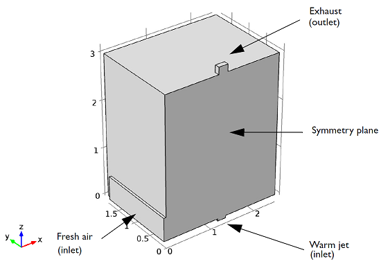
In this geometry, warm air of 45°C enters the room at a slow volumetric flowrate of 0.028 m3/s. The cool air, at a temperature of 21°C, flows into the room at 0.05 m3/s. From this data, we can determine whether there is forced convection or natural convection of heat occurring within the chamber, and whether the flow is turbulent or laminar. Forced convection of heat occurs if:
where g is gravity, \alpha is the coefficient for thermal expansion, T is the temperature, U the velocity, and L the length. Using characteristics figures, we can determine the type of convection taking place in the system. We can assume that the air can be approximated as an ideal gas in which case \alpha= 1/T, U can be approximated as 1 m/s, the temperature difference as 20 K, and the length as 2 m. This gives us a value of 1.3, demonstrating that convection within the system is natural convection.
Knowing that the convection within the system is natural convection, we can then use the Grashof number to determine the turbulent nature of the flow field:
Using the same figures as before, this gives us a value of 2 x 10¹⁰, indicating that the flow within the system is turbulent.
Fluid Flow and Temperature Analysis
The figure below to the left shows a streamline plot of the temperature within the system, while the figure below to the right shows the isosurfaces of the temperature field:

Streamlines show the velocity field while their color indicates the temperature distribution. Click to enlarge.

Isosurfaces of the temperature. Click to enlarge.
In these plots, we can see that there is strong thermal stratification along the vertical axis at z≈1m followed by a complex recirculation pattern. From a qualitative point of view, this model demonstrates the presence of both drafts and thermal stratification, phenomena that often occur and interact in such a system. Further analysis would need to be conducted on the model in order to investigate the possibility of reducing both thermal stratification and drafts without compromising the strength of the upward convective currents that remove air contaminants. Different geometries and boundary conditions need to be tested to decrease drafts, such as using radiant chilled ceilings, which can be explored with the help of simulation before deploying the final design.
Model Download
- Download the Displacement Ventilation of Air in a Room model from the Model Gallery
- Check out the book: System Performance Evaluation and Design Guidelines for Displacement Ventilation by Qingyan Chen and Leon R. Glicksman
- Read the paper: “Displacement ventilation environments with chilled ceilings: thermal comfort design within the context of the BS EN ISO7730 versus adaptive debate“


Comments (0)