Chemical Reactions and Soot Build-Up in a Diesel Filter
Application ID: 1394
In this tutorial, a filter system for a diesel engine is modeled, including a soot layer development and oxidization. The build-up of the layer is held in check by both catalytic and non-catalytic reactions, where carbon is oxidized to carbon monoxide and carbon dioxide, which in turn passes through the membrane.
A filter system's efficiency and durability is closely related to the manner in which it removes soot deposits from the porous filter walls. One approach involves introducing cerium additives to the fuel. Cerium oxide species are subsequently present in the soot layer, acting as a catalyst in carbon-oxidation reactions. Under these conditions, it is possible to remove carbon deposits in the filter without increasing the exhaust temperature. Five reactions and their accompanying kinetics are included in the mass balances.
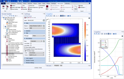
Two strategies are used to investigate this system. First, an ideal model of the system using the Reaction Engineering interface is utilized. This includes modeling of an ideal tubular (plug flow) isothermal reactor with the reaction kinetics only accounted for. The second strategy uses a space-dependent (2D) approach using four physics interfaces in the Chemical Reaction Engineering Module:
- Free and Porous Media Flow (fluid flow)
- Transport of Diluted Species (material balance)
- Heat transfer in Fluids (energy balance)
In this part the position of the top boundary, as a result of the soot build-up, is also explicitly solved for using a Moving Mesh feature.
Results for the first strategy show that the catalytic reactions dominate the oxidation of carbon, which decreases with increasing temperature. Further, results from the 2D model show that although the oxidation of carbon is an exothermic reaction, the catalytic steps are endothermic. Additionally, the carbon oxidation is not sufficient to keep the soot layer from growing.
この model の例は, 通常次の製品を使用して構築されるこのタイプのアプリケーションを示しています.
ただし, これを完全に定義およびモデル化するには, 追加の製品が必要になる場合があります. さらに, この例は, 次の製品の組み合わせのコンポーネントを使用して定義およびモデル化することもできます.
アプリケーションのモデリングに必要な COMSOL® 製品の組み合わせは, 境界条件, 材料特性, フィジックスインターフェース, パーツライブラリなど, いくつかの要因によって異なります. 特定の機能が複数の製品に共通している場合もあります. お客様のモデリングニーズに適した製品の組み合わせを決定するために, 製品仕様一覧 を確認し, 無償のトライアルライセンスをご利用ください. COMSOL セールスおよびサポートチームでは, この件に関するご質問にお答えしています.