Ohmic Losses and Temperature Distribution in a Passive PEM Fuel Cell
Application ID: 8553
In small PEM fuel cell systems (in the sub-100 W range) no active devices for cooling or air transport are normally used. This is due to the desire to minimize parasitic power losses from pumps and fans, and to reduce the system complexity, size, and cost. The reactants at the cathode are therefore transported by passive convection/diffusion. Also the heat dissipation occurs by passive transport mechanisms to the surrounding environment.
When designing the air side of a passive fuel cell the goal is to ensure an even current density and heat profile over the cell for various surrounding temperatures and current loads.
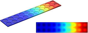
The holes in the cathode cover plate should typically be large in order to provide good reactant transport to the electrode, but the hole-to-solid material ratio may not be too large since the structural rigidity and electron conductivity of the plate also have to be maintained. Large air holes will also cause high local ohmic losses in the GDL. This example models the current density and heat profile over a passive PEM fuel cell.
この model の例は, 通常次の製品を使用して構築されるこのタイプのアプリケーションを示しています.
ただし, これを完全に定義およびモデル化するには, 追加の製品が必要になる場合があります. さらに, この例は, 次の製品の組み合わせのコンポーネントを使用して定義およびモデル化することもできます.
アプリケーションのモデリングに必要な COMSOL® 製品の組み合わせは, 境界条件, 材料特性, フィジックスインターフェース, パーツライブラリなど, いくつかの要因によって異なります. 特定の機能が複数の製品に共通している場合もあります. お客様のモデリングニーズに適した製品の組み合わせを決定するために, 製品仕様一覧 を確認し, 無償のトライアルライセンスをご利用ください. COMSOL セールスおよびサポートチームでは, この件に関するご質問にお答えしています.