FEM Resistor in Circuit
Application ID: 109011
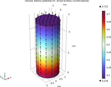
HowTo: Using the EC External I-Terminal
The External Couplings in the CIR interface has two flavors that can be used. External I vs. U and External I-terminal. The former has two nodes (it represents a differential external voltage measurement) and when coupling to an EC Terminal feature, you need to have a local ground in the EC model. The latter is single node and thus you need two instants of it and two Terminal features in the EC interface. In the former case, there are two different (shifted) electric potentials (one in CIR and one in EC). In the latter case, there is one consistent electric potential definition in the model and just one ground reference. Voltage drops and currents are of course the same in both models. The attached models illustrate the concepts.
この model の例は, 通常次の製品を使用して構築されるこのタイプのアプリケーションを示しています.
ただし, これを完全に定義およびモデル化するには, 追加の製品が必要になる場合があります. さらに, この例は, 次の製品の組み合わせのコンポーネントを使用して定義およびモデル化することもできます.
- COMSOL Multiphysics® and
- either the AC/DC モジュール, MEMS モジュール, or プラズマモジュール
アプリケーションのモデリングに必要な COMSOL® 製品の組み合わせは, 境界条件, 材料特性, フィジックスインターフェース, パーツライブラリなど, いくつかの要因によって異なります. 特定の機能が複数の製品に共通している場合もあります. お客様のモデリングニーズに適した製品の組み合わせを決定するために, 製品仕様一覧 を確認し, 無償のトライアルライセンスをご利用ください. COMSOL セールスおよびサポートチームでは, この件に関するご質問にお答えしています.