静電気
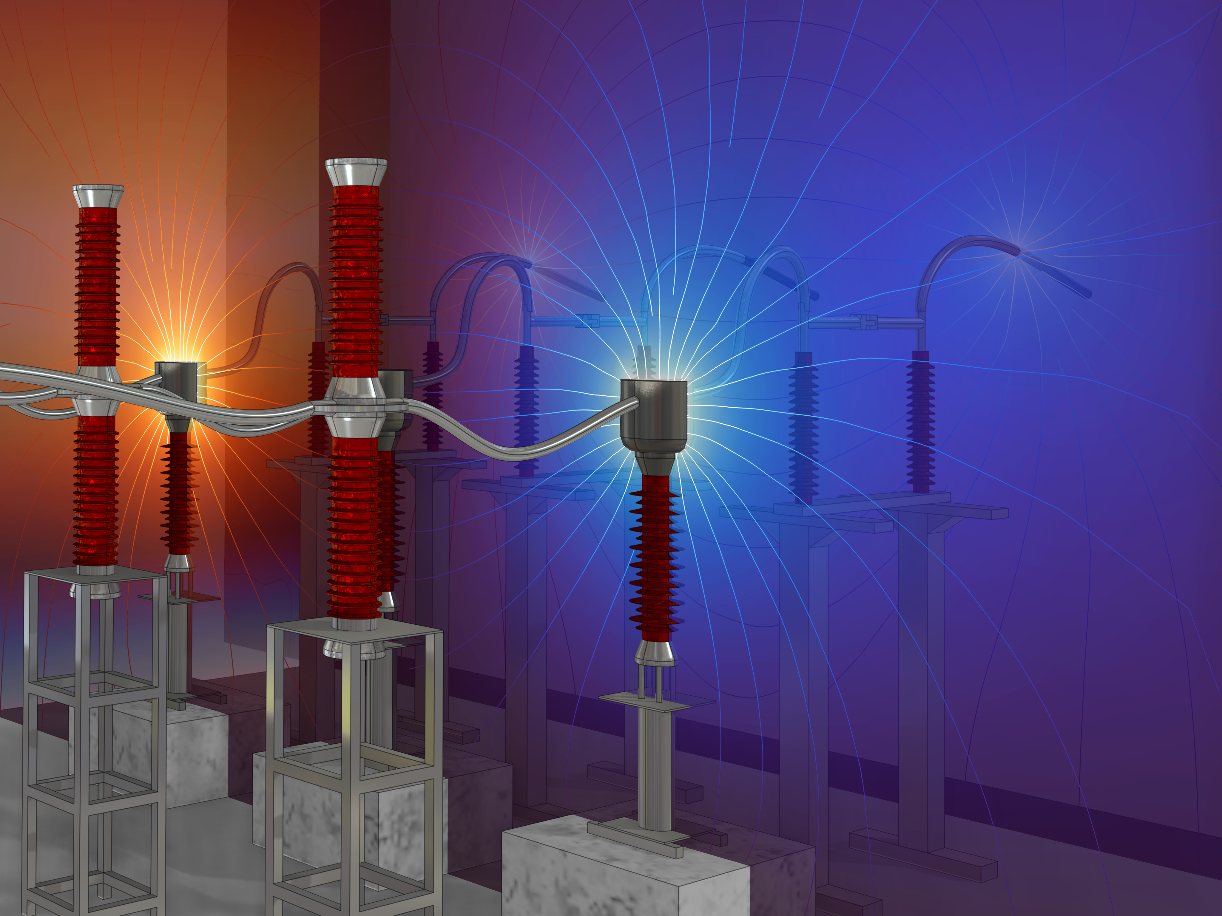
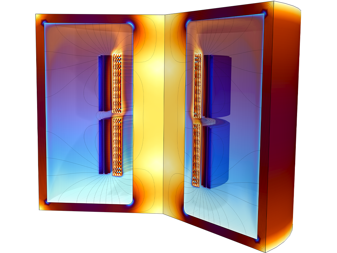
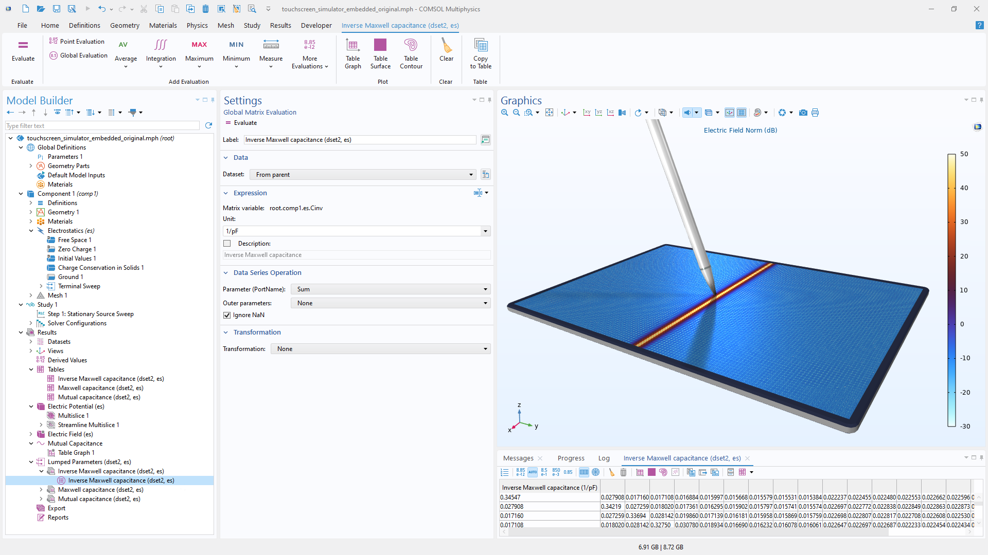
静電気力計算を使用して, 容量性機器と電気絶縁体を解析します. このアプローチは, 電流が流れておらず, 電界が電位と電荷分布によって決定される誘電体に適用できます. 電位を解く方法として, 有限要素法 (FEM) と境界要素法 (BEM) があり, これらを組み合わせることで有限要素-境界要素のハイブリッド法を用いることができます. 計算された電位場に基づいて, 静電容量マトリックス, 電場, 電荷密度, 静電エネルギーといった量を計算できます.
低周波電磁気と電気機械部品のシミュレーション
定常低周波レンジの電磁システムとプロセスの解析には, 強力で柔軟なシミュレーションツールが必要です. COMSOL Multiphysics® プラットフォームの AC/DC モジュールアドオンには, 幅広いモデリング機能と EMI/EMC および電磁場解析のためのマックスウェル方程式を解く数値解法を提供します.
COMSOL® ソフトウェアのマルチフィジックス機能によって, 電磁気モデル上の熱伝導, 構造力学, 音響など他の物理的効果の影響を調べることができます.
COMSOL へお問い合わせ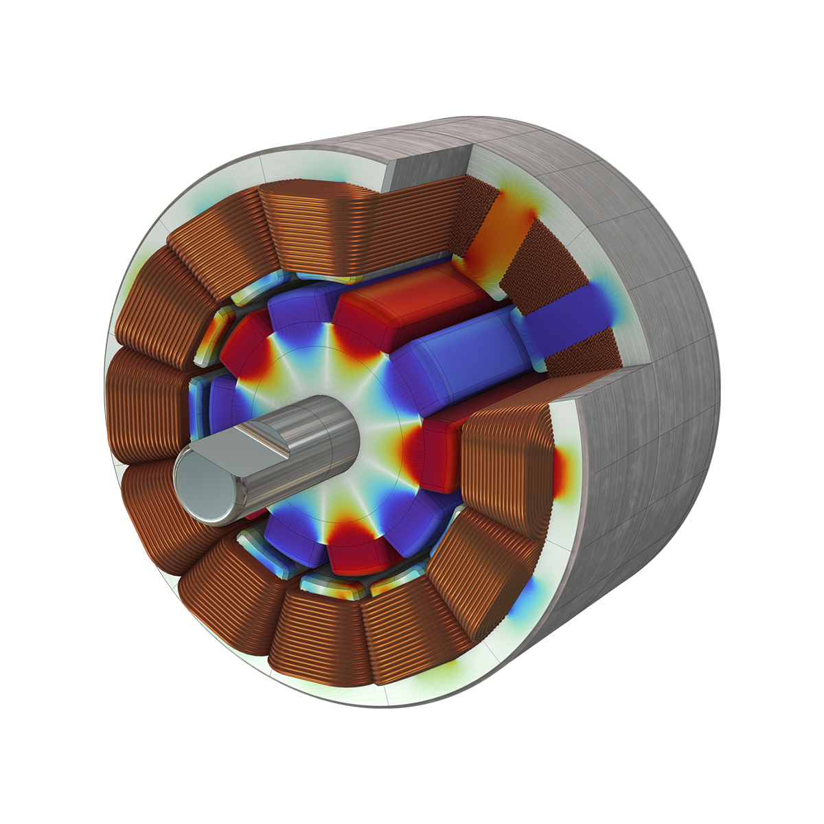
静電気力計算を使用して, 容量性機器と電気絶縁体を解析します. このアプローチは, 電流が流れておらず, 電界が電位と電荷分布によって決定される誘電体に適用できます. 電位を解く方法として, 有限要素法 (FEM) と境界要素法 (BEM) があり, これらを組み合わせることで有限要素-境界要素のハイブリッド法を用いることができます. 計算された電位場に基づいて, 静電容量マトリックス, 電場, 電荷密度, 静電エネルギーといった量を計算できます.
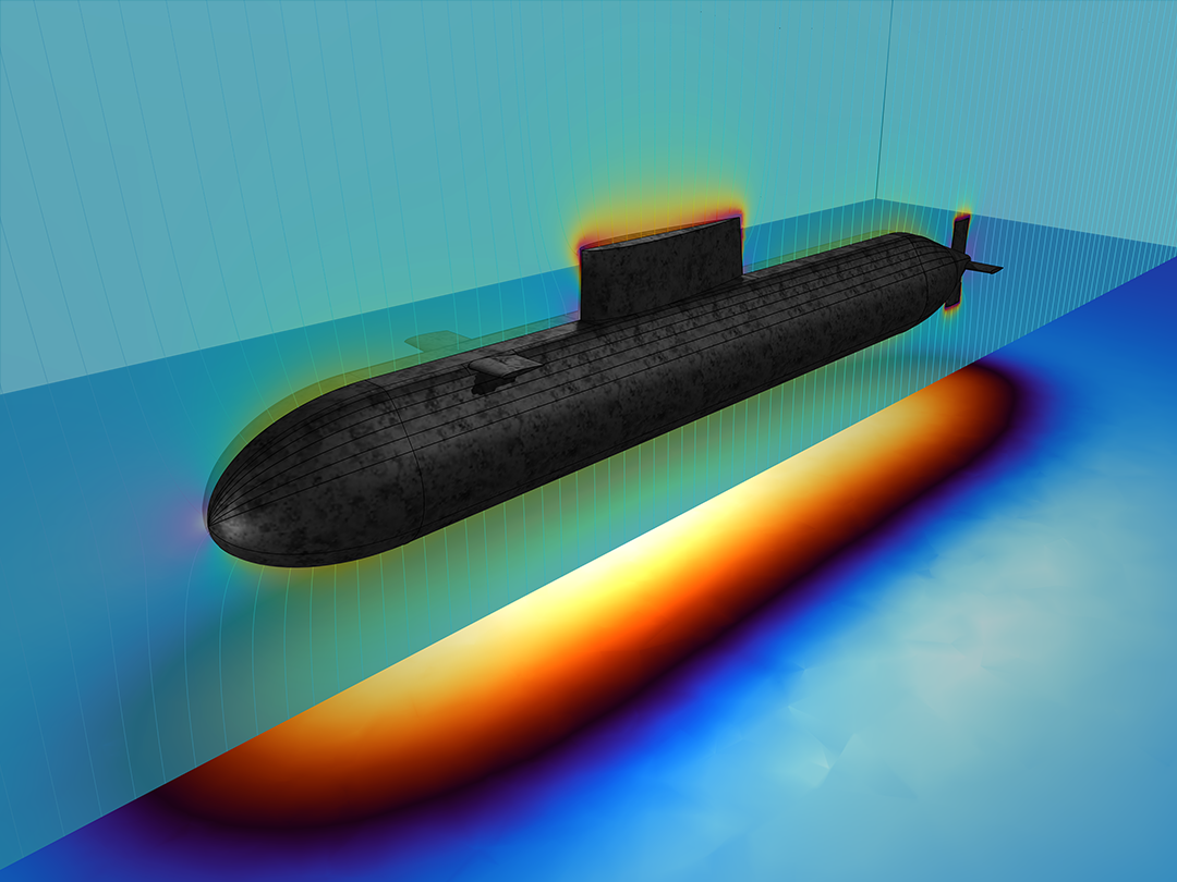
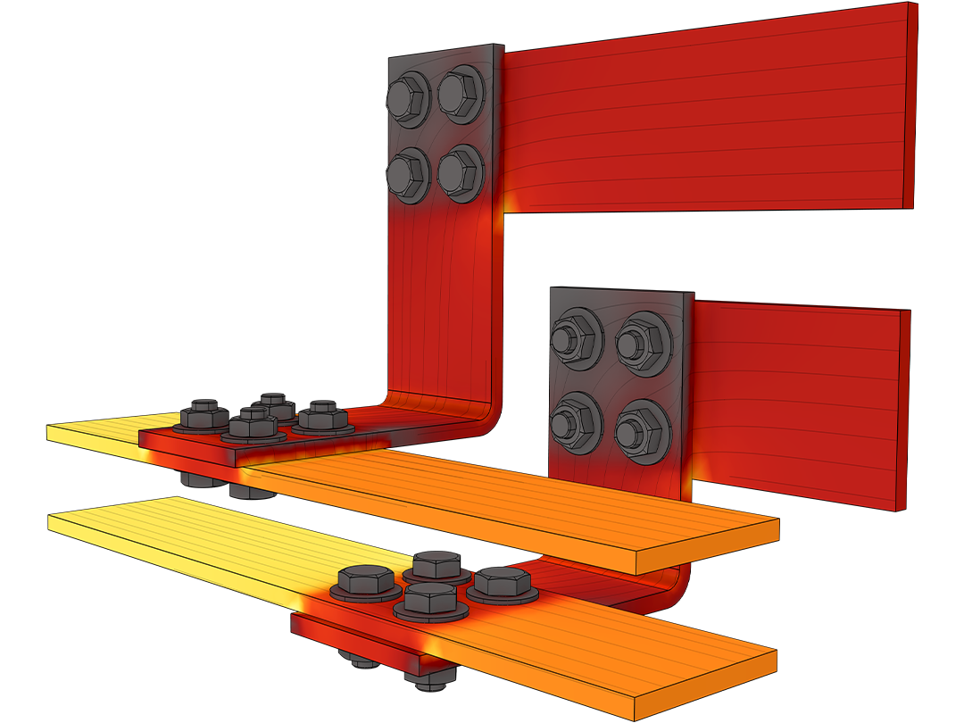
DC (直流), 過渡, または AC (交流) 電流をモデル化することにより, 抵抗性および導電性機器を効率的に解析できます. 定常低周波条件下で, 磁場が無視できる場合, 正確な結果を得るには電流のモデリングで十分です. オームの法則に基づく計算は, 電位を解くことによって非常に効率的になります. 結果として生じる電位場に基づいて, 抵抗, コンダクタンス, 電界, 電流密度, および電力損失といったさまざまな量を計算できます.
AC/DC モジュールでは, 定常, 周波数領域, 時間領域, 小信号解析のいずれも可能です. 時間領域と周波数領域では, 容量変化の影響を考慮することもできます.

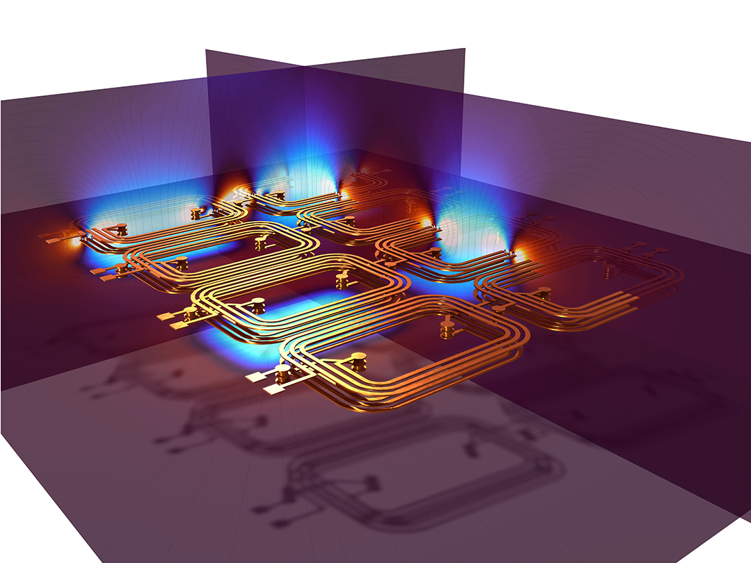
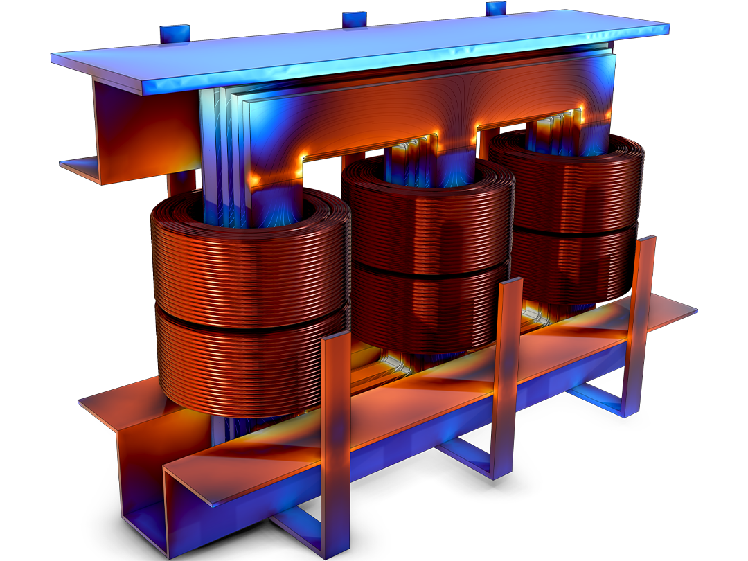
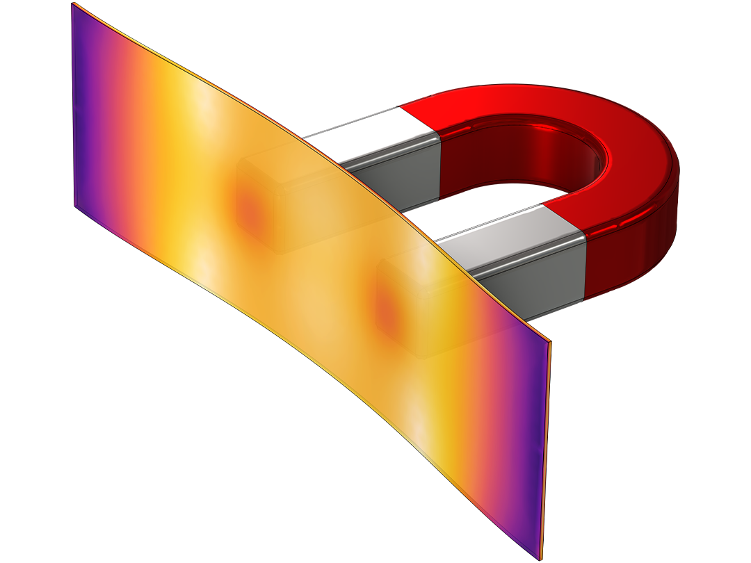
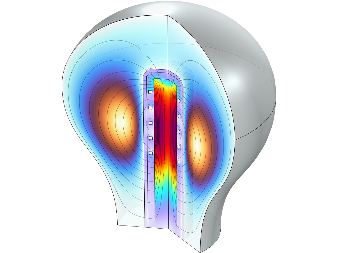
静磁場, 寄生インダクタンス, およびコイル, 導体, 磁石にかかる力を計算します. さまざまな非線形磁性材料を含む広範な材料データベースから選択するか, 独自の非線形材料を定義することができます. また, 電流か磁性材料, またはその両方が存在する, といった条件に応じてさまざまな定式化が可能です.
有限要素法 (FEM) と境界要素法 (BEM) はどちらも, 電流がない場合の静磁気に使用できます. また, これらを組み合わせて有限要素-境界要素のハイブリッド法を使用することも可能です.
最も一般的なケースである, 電流と磁性材料の両方が存在する場合, ベクトル場の定式化により, 電位と入力電流を定義し, 電流密度分布, 磁場, 磁力, 電力損失, 相互インダクタンスを計算します.
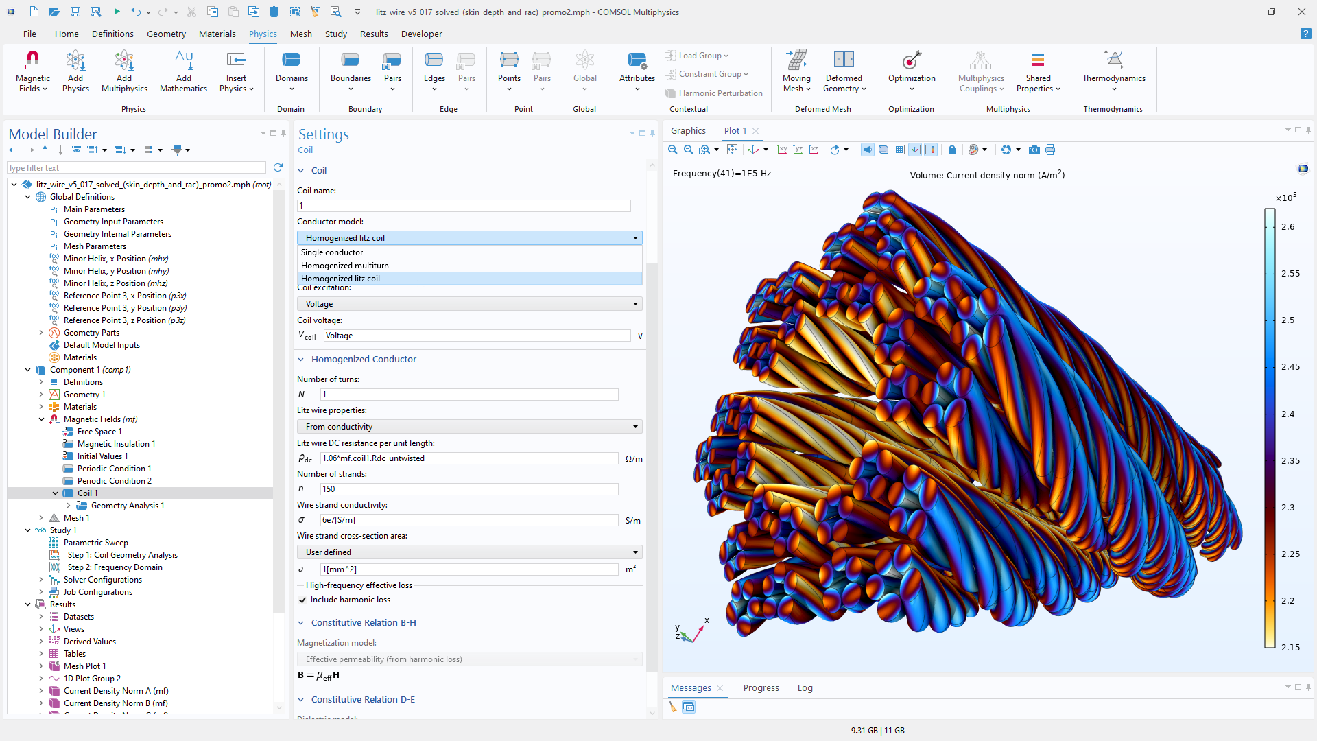
コイルのモデル化には, 各ワイヤー内の正確な電流分布を計算する明示的な方法と, 巻数の多いコイルに非常に有効な均質化された方法があります. 複雑な形状のコイルも, コイルの電流分布を計算することによって自動的に処理されます.
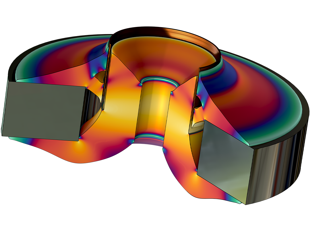
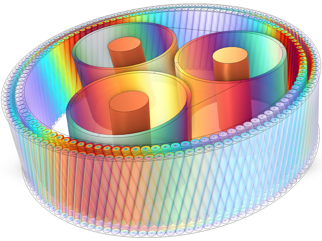
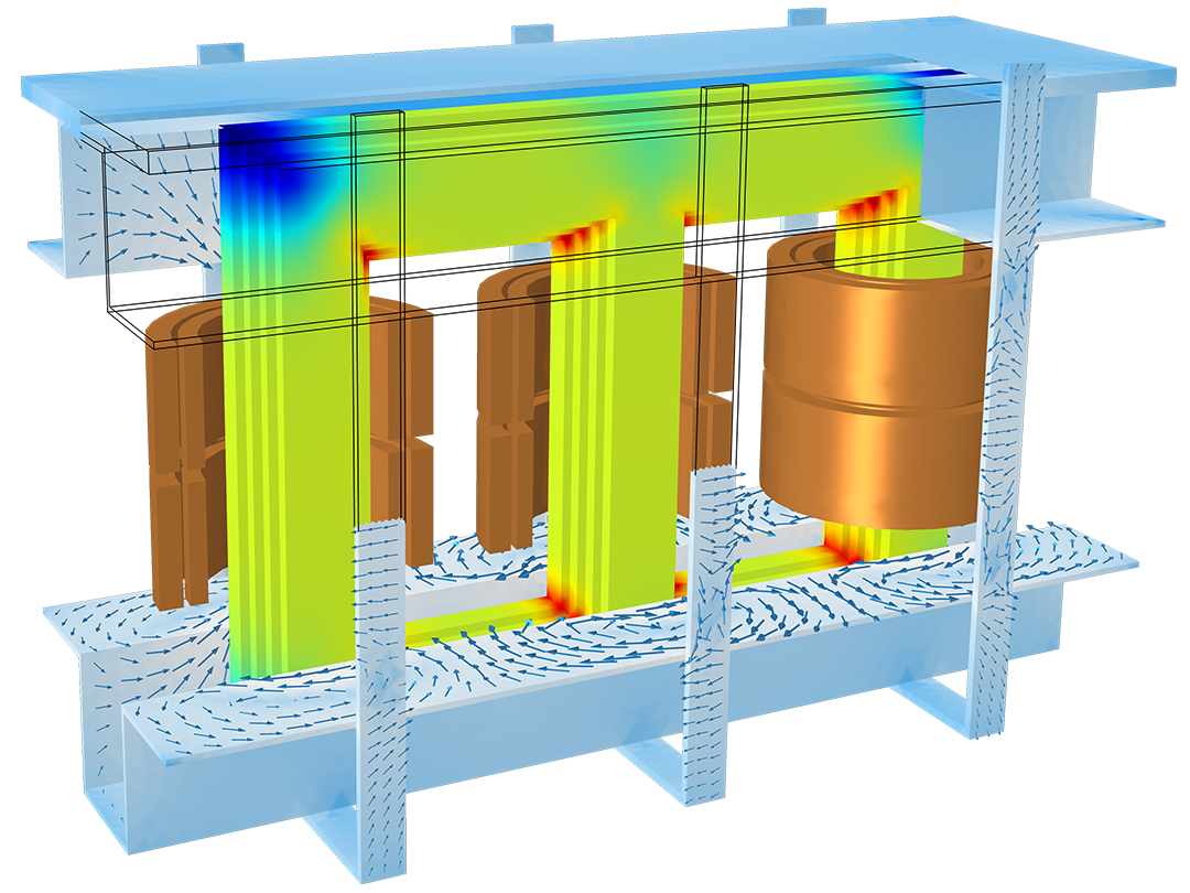
電流と磁場がカップリングしている電気部品を解析するために, 完全電磁場モデリングを使用できます. 誘導効果が重要となる時間依存問題では, 磁場が電流を誘起し, その電流がさらに磁場を生成します.
表皮効果や近接効果, ローレンツ力 (運動による誘導), 共振, クロストークなどの電気力学的効果を解析できます.周波数領域および時間領域の両方で, 2Dおよび3Dのモデリングに対応しています. 超伝導体の過渡磁気モデリングには専用の定式化も用意されています.
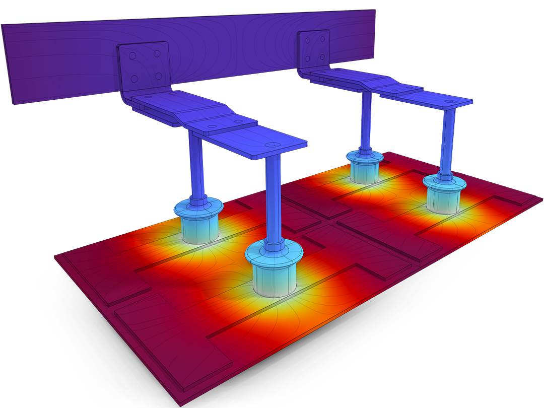
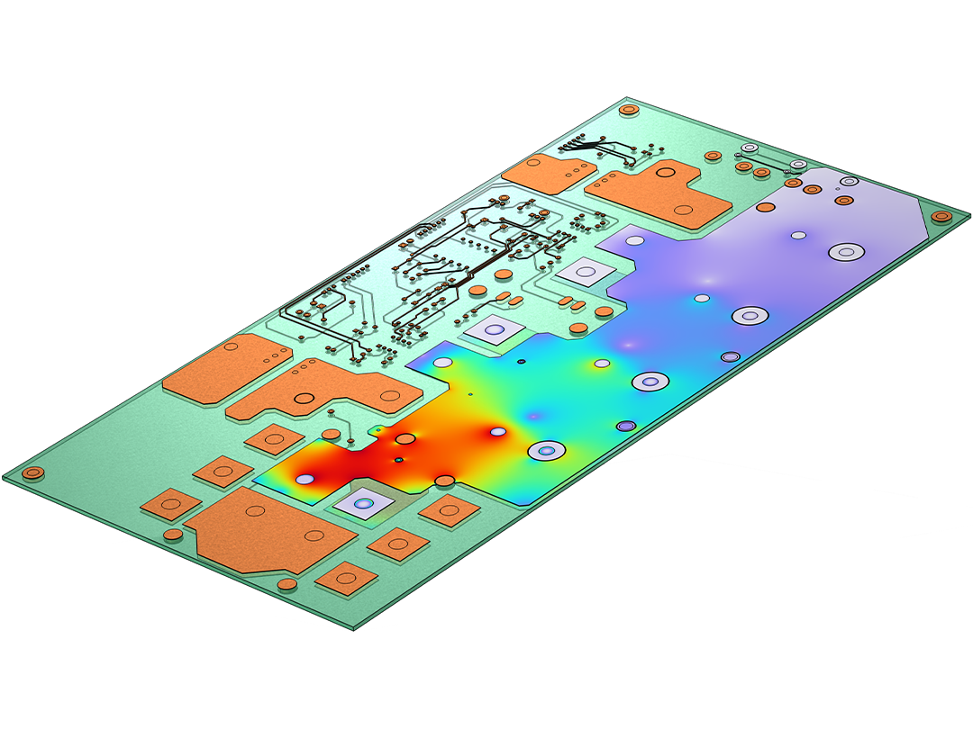
代表的な用途には, コイル, 誘導充電器およびヒーター, スイッチ, バスバー, トランス, PCBの過渡効果, シールド, クロストーク, 超伝導デバイス, 磁気流体力学, 非破壊検査 (NDT) などがあります.
電磁気シミュレーションは, 伝熱モジュール, 構造力学モジュール, CFDモジュール など, 他の任意のアドオン製品と連成できます.
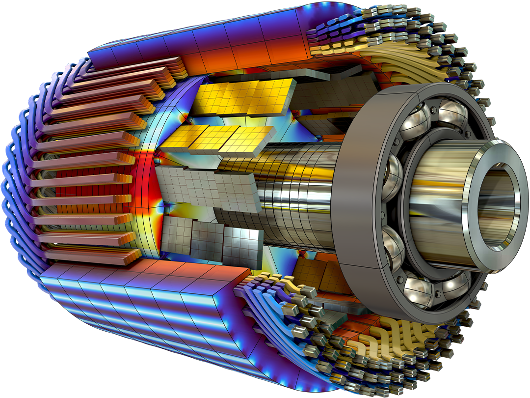
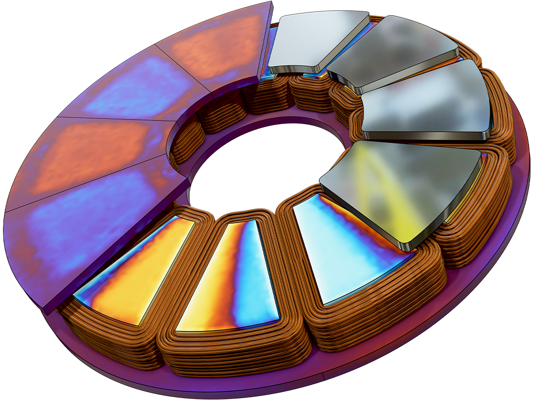
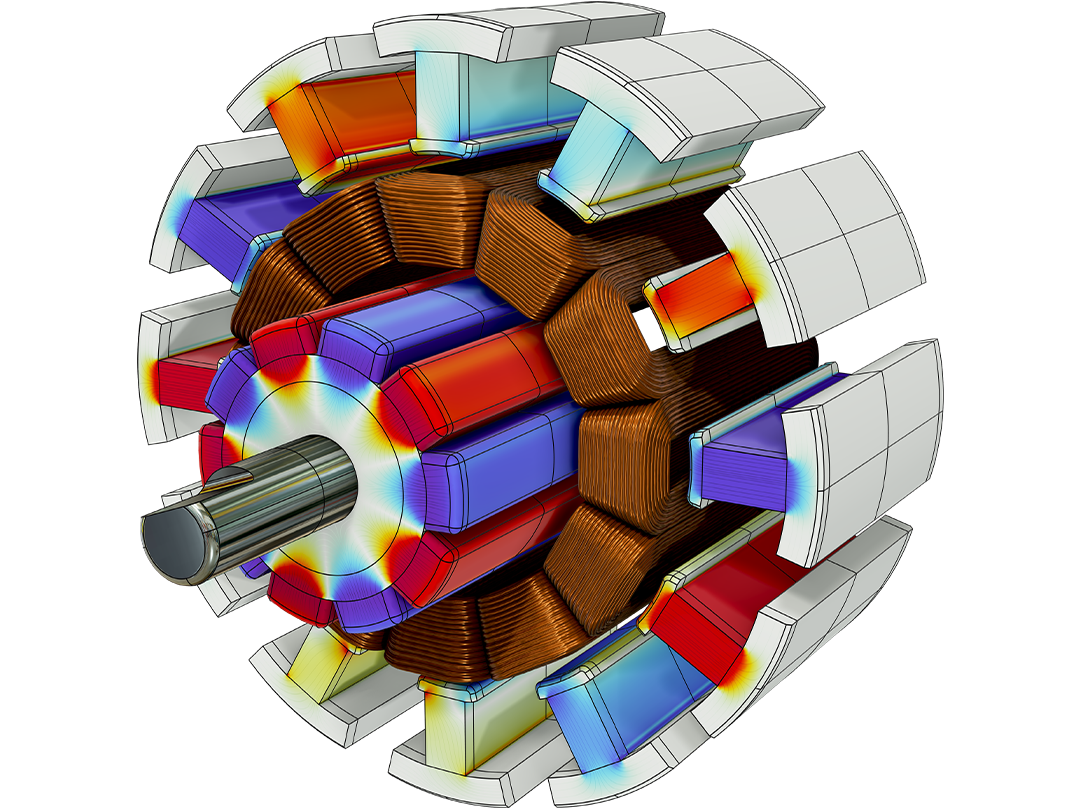
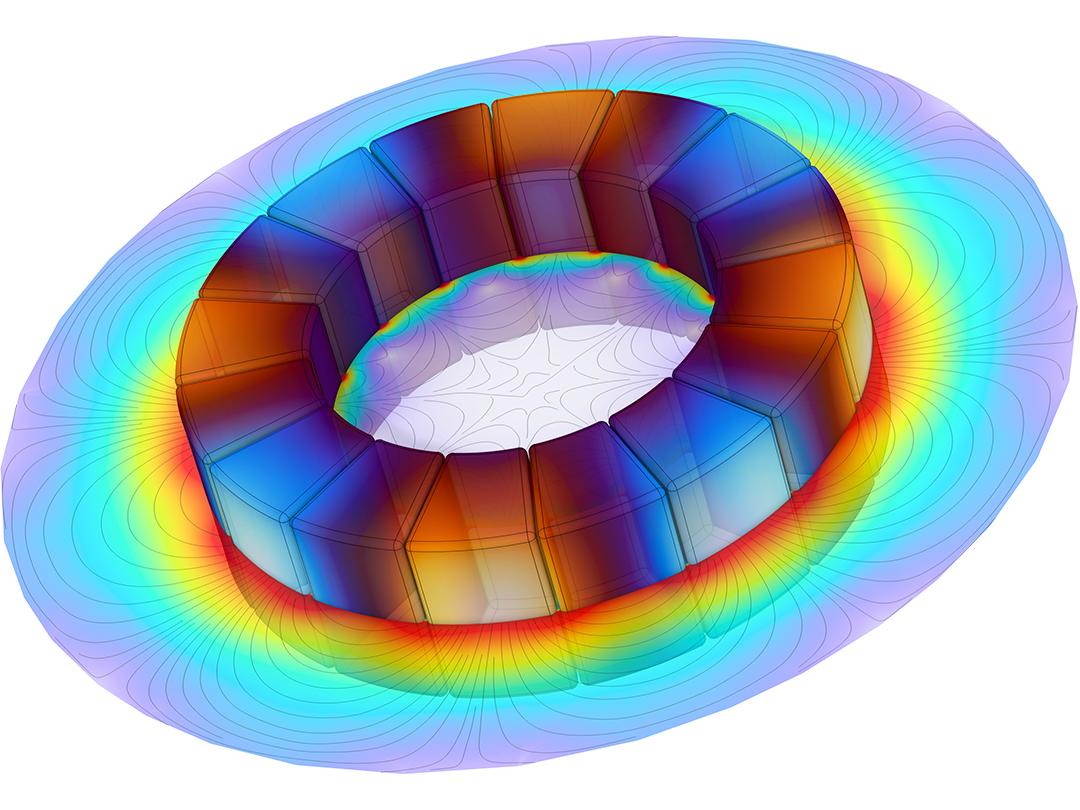
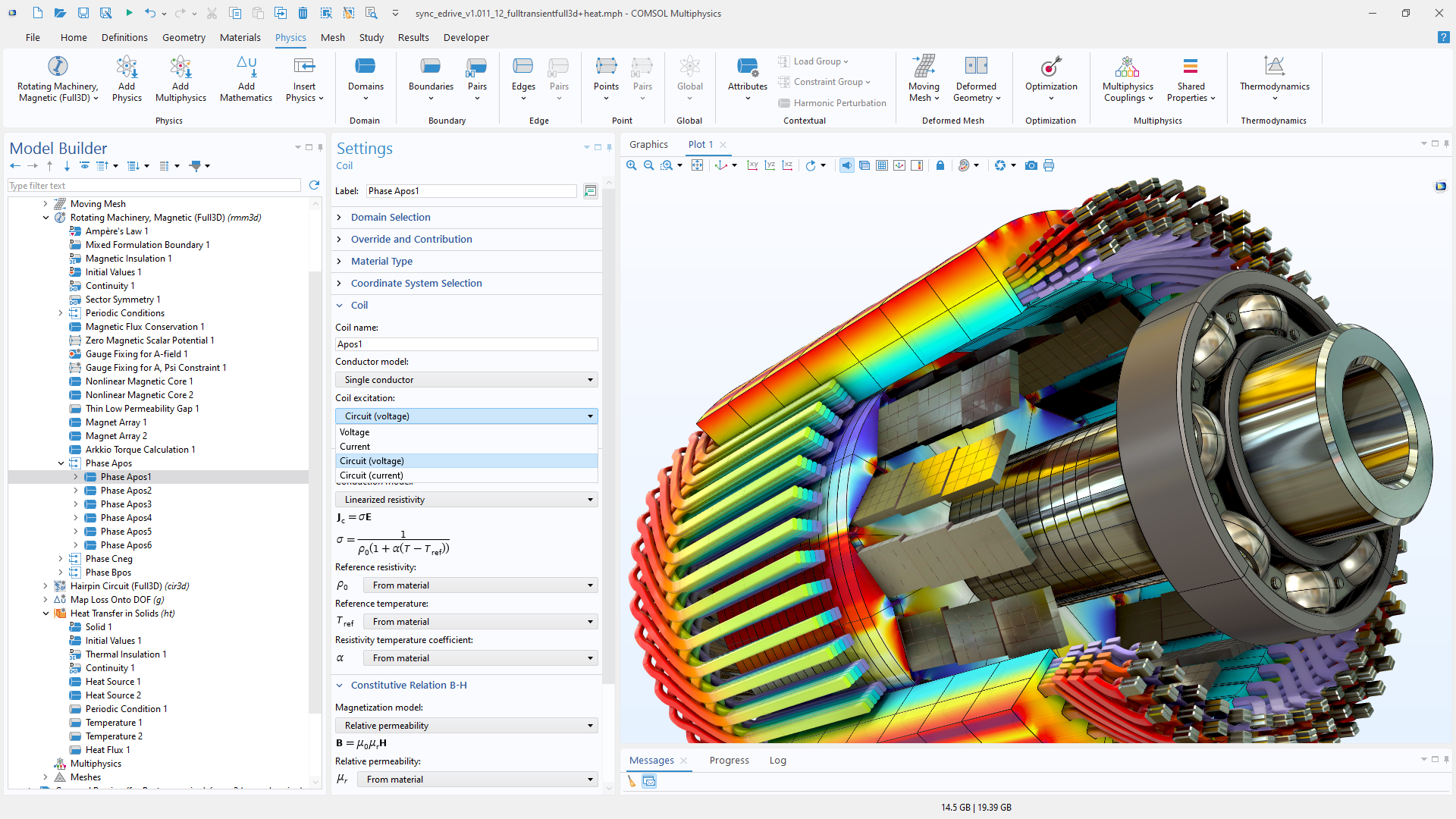
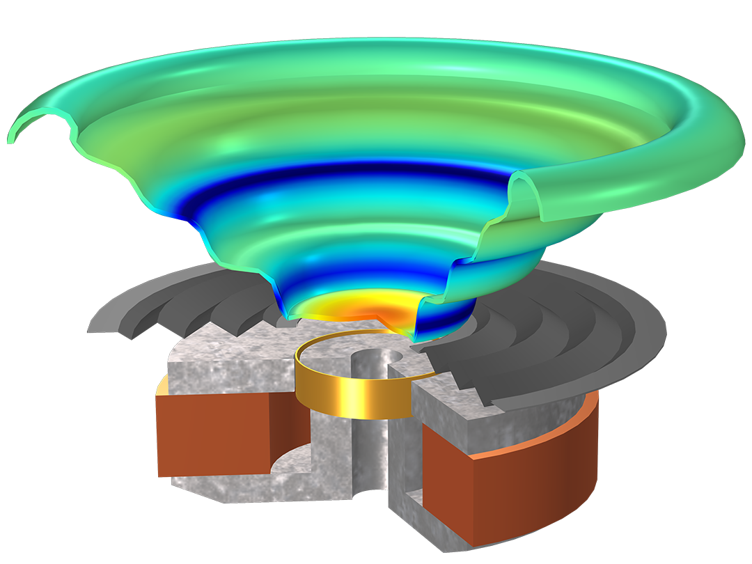
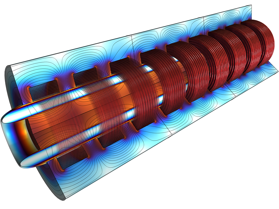
電気機械のモデリングにより, モーター, 発電機, アクチュエータの最適化が可能になります. 組み込み機能により, 誘導モーターおよび永久磁石モーターについて, トルク, 磁石中の渦電流損失, 力, 誘導電流, 機械的負荷の影響などを評価できます. 電磁力およびトルクの影響下で, 剛体および柔軟体のダイナミクスを解析できます.
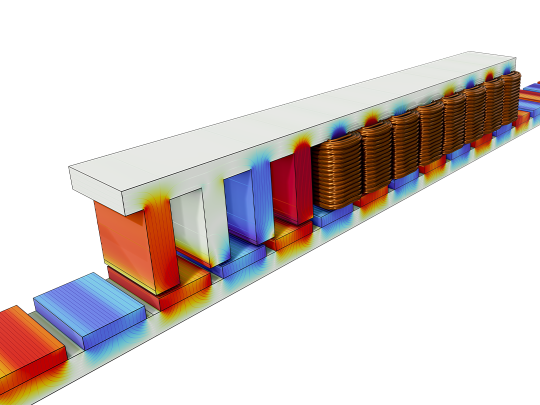
特化した機能により, ラジアルフラックスモーターからハイブリッド軸ラジアルフラックスロータ, クローポールローター, 管状リニア機械まで, さまざまな機械タイプの設計をサポートします. プランジャー, ソレノイド, スイッチ, アクチュエーターなどのデバイスに重要な直線運動も, 移動メッシュ機能を用いてモデル化できます.
AC/DCモジュールを他のフィジックスモジュールと組み合わせることで, 変形のための構造力学, ロータダイナミクス, 熱管理のための伝熱, 騒音および振動のための音響, 冷却流路最適化のためのCFDを含むマルチフィジックス解析を実行できます.
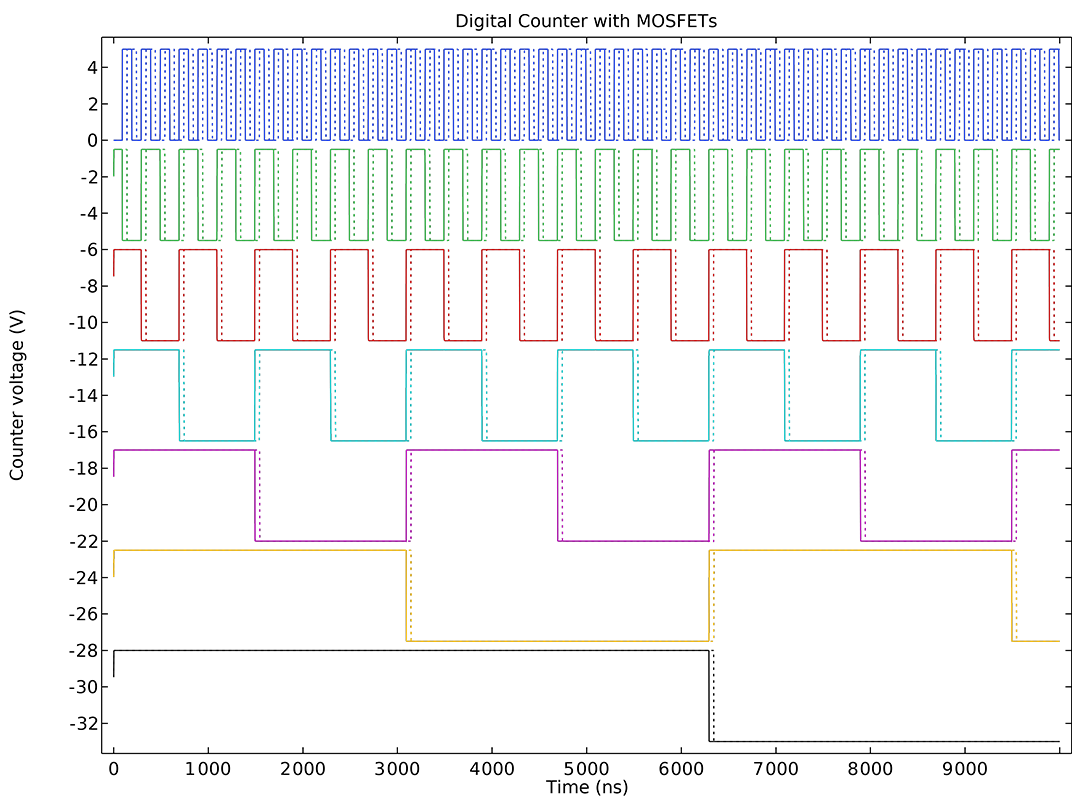
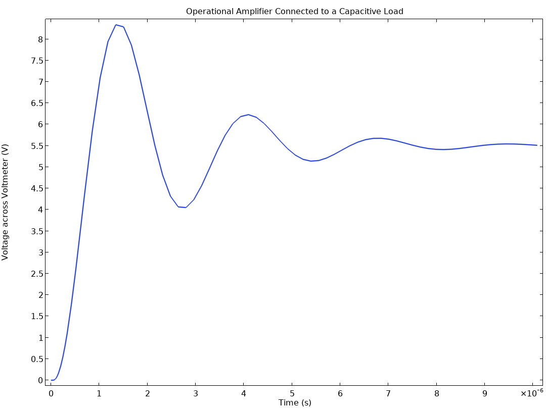
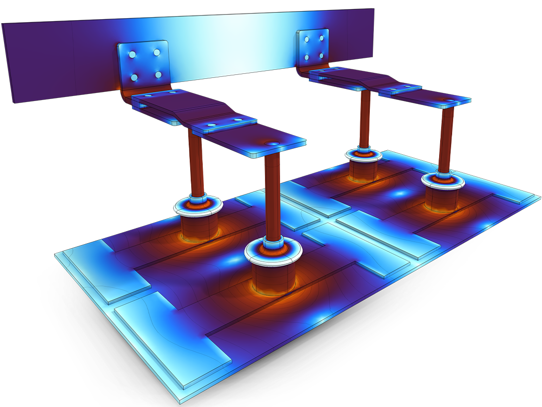
AC/DCモジュールは, 集中系および回路を解析するための専用フィジックスインターフェースを提供します.このインターフェースにより, 電圧源および電流源, 抵抗, コンデンサー, インダクター, トランス, ダイオード, トランジスタなどの一般的なコンポーネントをモデル化できます.より複雑な要素はサブ回路を用いて追加できます. 回路はSPICEネットリスト形式でインポートおよびエクスポートできます.
回路モデルは2Dまたは3Dの有限要素モデルと組み合わせることができます. 抵抗, キャパシタンス, インダクタンスの行列は有限要素モデルから抽出でき, それを用いて効率的な集中回路表現を作成できます. 回路と有限要素モデルの直接連成により, 例えば誘導充電器における発振回路やモーター制御回路のシミュレーションが可能です. 詳細な有限要素領域を回路表現に縮小するハイブリッドサブモデリングも可能です.
AC/DC モジュールには今ページで紹介しているさまざまな性能に特化した機能が備わっています.
AC/DC モジュールには, 上記の電磁気学の各分野に対応したユーザーインターフェースが組み込まれており, 特定のモデリング目的のバリエーションを提供します. これらのインターフェースでは, ドメイン方程式, 境界条件, 初期条件, 事前定義されたメッシュ, 定常および過渡解析のソルバー設定を持つ事前定義されたスタディ, および事前定義されたプロットと計算値がセットで定義されます.
また, 異なるインターフェースを接続し, 簡単にモデル化する機能もあります. これは, インダクター, コイル, モーターに便利です.
AC/DCモジュールには, 強磁性体, フェリ磁性体, 軟磁性体 (B–H曲線), 硬質磁性体 (永久磁石) を含む包括的な磁性材料データベースが含まれています.非線形材料モデル, 有効B–H曲線および複素透磁率を用いた周波数領域での磁気損失モデル, さらに Jiles–Atherton モデルに基づく異方性ヒステリシスに対応しています.
積層電磁鋼板のモデリングには, 積層コアモデリング機能や Steinmetz および Bertotti などの経験的損失モデルが用意されており, 個々のラミナを分解せずに現実的な損失推定が可能です.
材料は空間依存, 異方性, 時間依存, 場依存な物性として定義できます.異方性非線形性, 永久減磁, キュリー効果などを含むユーザー定義特性およびカスタム挙動のモデリングに完全に対応しています.
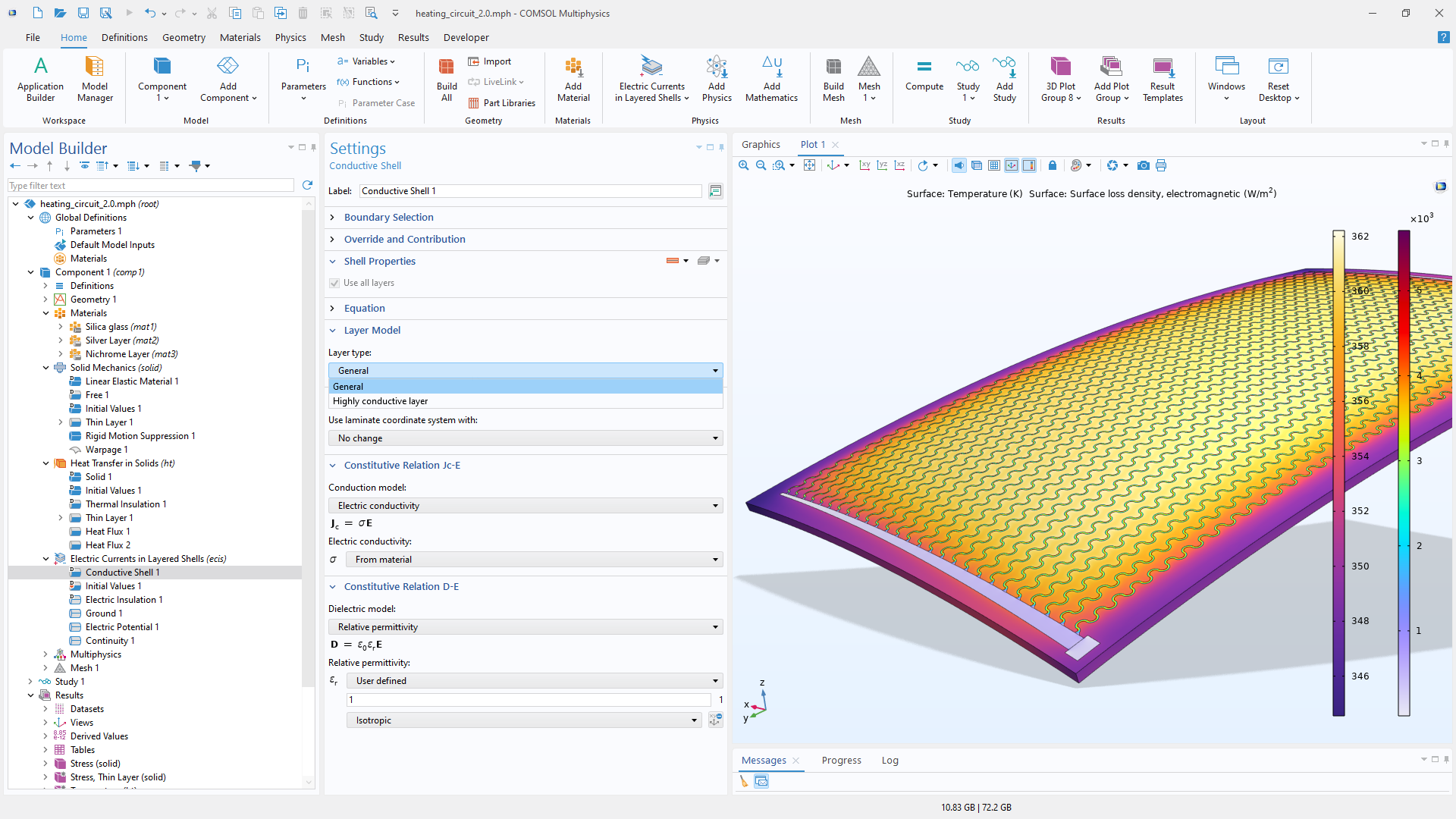
非常に薄い構造は, 直流, 静電, 静磁場, 誘導解析に対するシェル定式化を用いて効率的にモデル化できます. さらに, 多層シェル構造における直流のモデリングにも対応しています. 電磁シェルモデリングにより, 薄い体積領域を等価な物理挙動を持つゼロ厚さの境界条件に置き換えることで, ジオメトリ作成, メッシュ生成, 求解を大幅に簡略化できます.
高周波では表皮深さが小さくなり電流が導体表面に集中するため, 専用の境界機能によりさらに効率的な導体表現が可能です.
誘電体および弱導電材料については, 以下をサポートします:
組み込みの分散モデルには, マルチポール Debye, Cole–Cole, Havriliak–Negami モデルが含まれます.これらは生体組織モデリングやバイオエンジニアリング用途で特に重要です.
磁性材料と同じく導体および誘電体にも同様に柔軟性があります. ユーザー定義定式化により, 材料ライブラリを拡張してカスタム材料モデルを組み込むことができます.
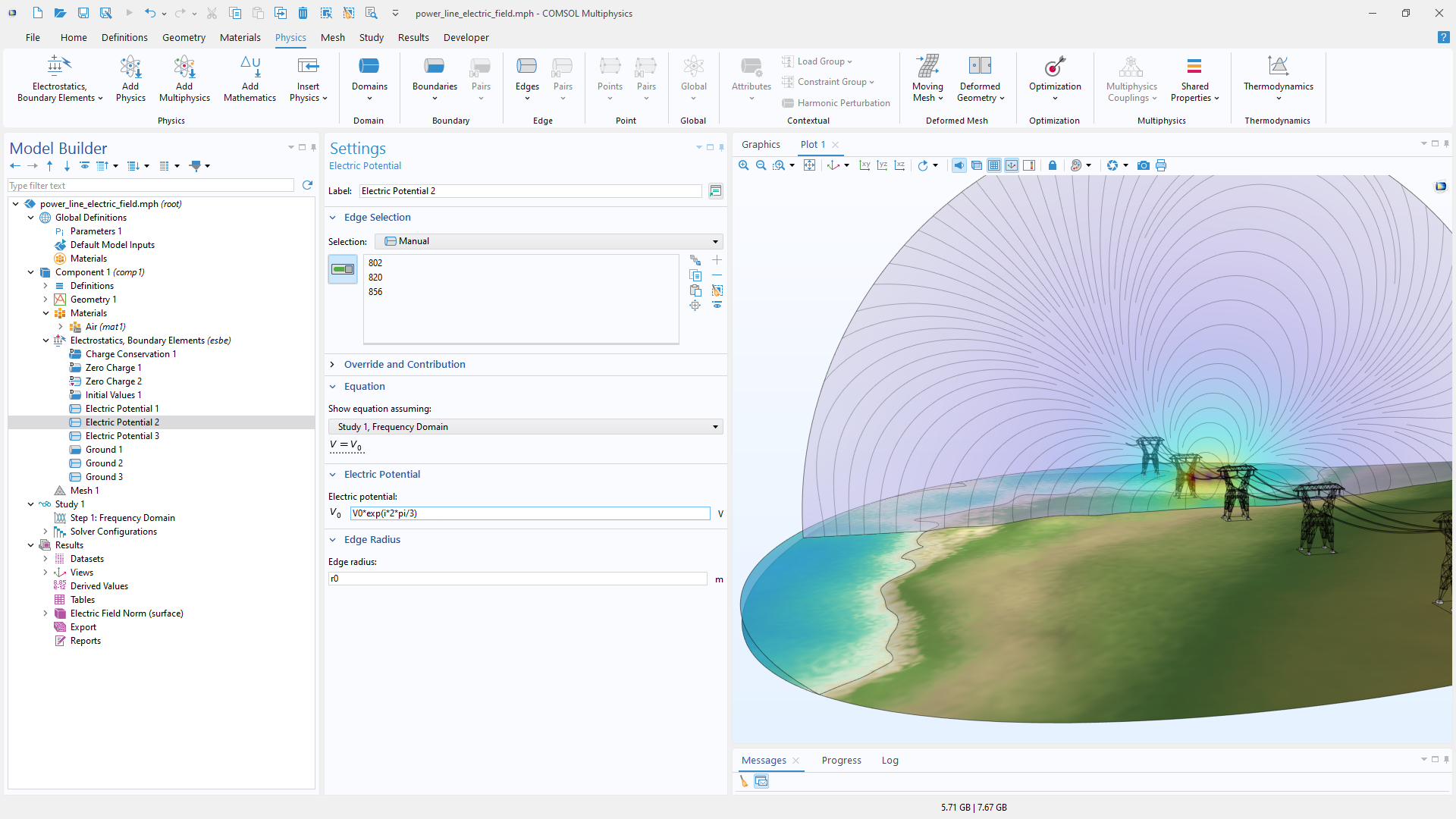
無限または大規模領域を正確にモデル化するために, 電場および磁場の両方の定式化に対して無限要素が利用可能です.静電場および静磁場解析では, 境界要素法 (BEM) が大規模または無限領域を表現するための代替手法を提供します.さらに, BEMは有限要素ベースのフィジックスインターフェースと連成でき, ハイブリッド BEM–FEM 解析が可能です.
AC/DC モジュールの電磁モデリング機能には, 電磁励起, 負荷, デバイス挙動を高精度にシミュレーションするための専用機能が含まれます.
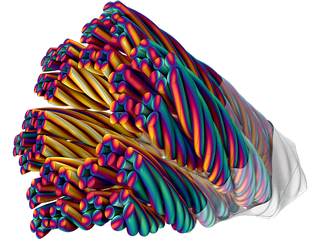
コイルモデリングツールは, 表皮効果および近接効果を伴う固体導体から, AC損失を最小化するために設計された撚り線束まで全て対応します. リッツ線, 密着巻きコイル, セグメント型高圧導体などの設計にも対応しています.
端子定義により, 浮遊電位, 測定点, 電気回路接続をサポートしながら, 電圧, 電流, 電荷を容易に指定できます. 分布容量およびインピーダンスのモデリングオプションにより, 誘電体または抵抗性コーティングを持つ電極を正確に表現できます.
汎用的な励起手法も用意されており, 接地面などの電圧拘束の指定や, 表面電流の直接定義が可能です.
導電材料は温度依存および電磁場依存の挙動の両方をサポートします. 電気力学条件下では, 表皮効果および近接効果を含めることも選択的に抑制することもでき, 積層鋼板, 巻線コイル, 撚り線束の効率的なモデリングが可能です. 特にリッツ線は, 個々の素線を分解することなく設計周波数以上でもモデル化できます.
コイル, 端子, ポート などの励起機能は, 以下の電気量に対する出力変数を自動的に提供します:
専用の周波数スイープ機能と最適化されたソルバー設定により, キャパシタンス, 抵抗, インダクタンス行列を効率的に抽出できます. この機能により, 詳細な有限要素モデルを簡略化された集中回路表現へ簡単に変換できます.
電磁力や総損失などの特定の物理量を計算するための専用機能も利用可能です.
豊富なカスタマイズ機能により, 解から得られる任意の量を評価, 積分, 微分できます. 多様な結果評価ツールにより, 解析に必要なデータを正確に抽出できます.
電磁現象は通常マルチフィジックス環境で発生するため, AC/DC モジュールは例えば次のような他のアドオン製品とのカップリングのための広範なオプションを提供します:
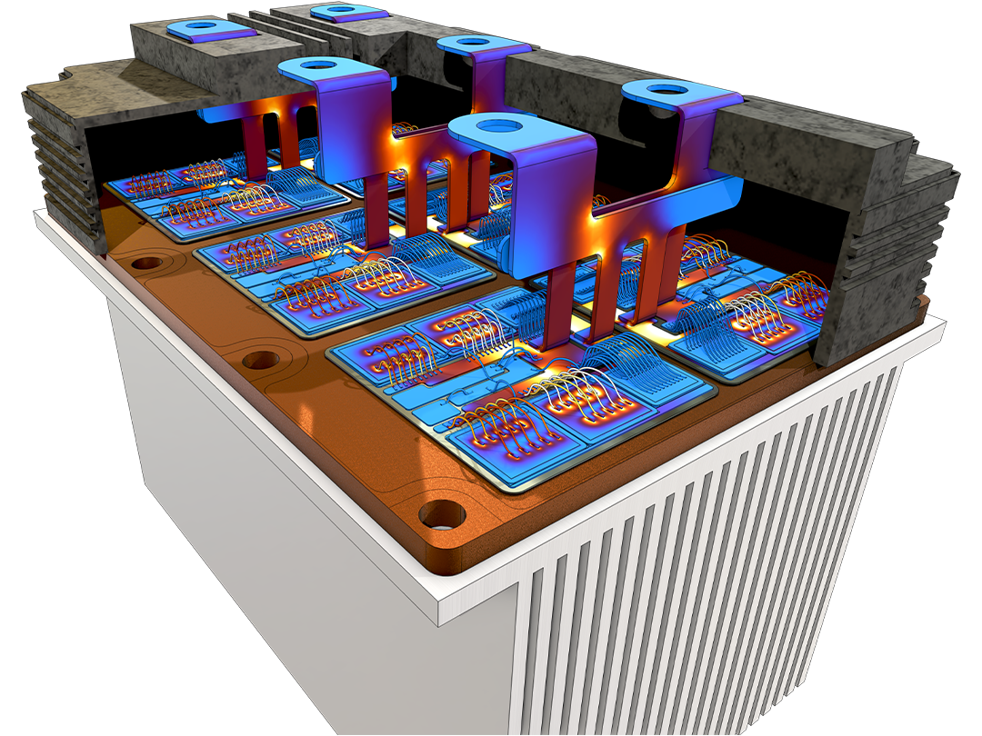
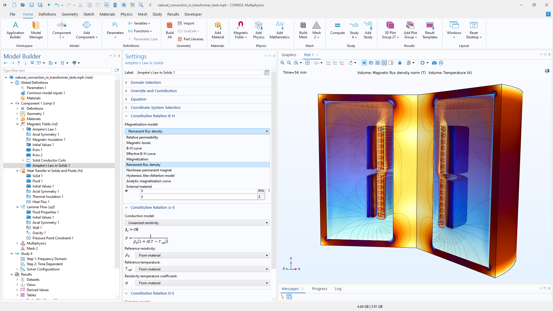
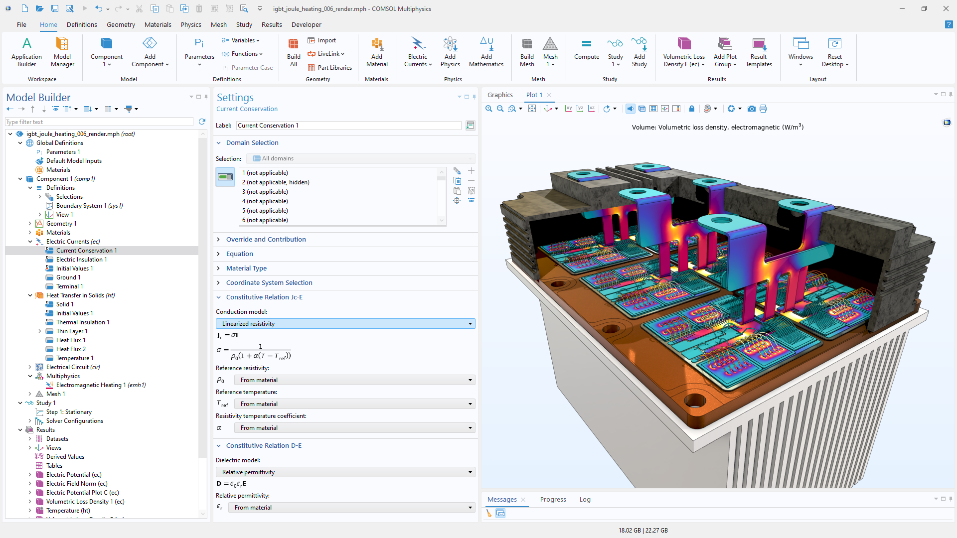
組み込みのマルチフィジックスカップリングにより, 磁気力学, 電気機械, ジュール加熱と熱膨張, 誘導加熱, 圧磁, 圧電, ピエゾ抵抗, 非線形磁歪, 電歪, 強誘電弾性, 熱電効果, 焦電効果, 磁気流体力学をモデル化できます.
これらに加えて, 手動でマルチフィジックスカップリングを定義し, 完全連成または逐次的アプローチで求解することも可能です.
電磁気部品は, 複数の物理現象に影響を与え, また影響を受けます. COMSOL Multiphysics® では, これはシングルフィジックスの問題をモデリングするのと変わりません.
固体, 流体, シェル, および積層シェルでのジュール加熱 (抵抗加熱とも呼ばれる).
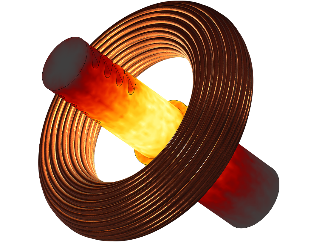
誘導加熱によるインライン誘導加熱器のモデル化, および金属加工.
接触させた金属片の間に流れる電流. 熱接触2 と機械的接触3とを合わせたもの.
有限要素法と境界要素法に基づく, 電磁応力, 力, およびトルクの計算.
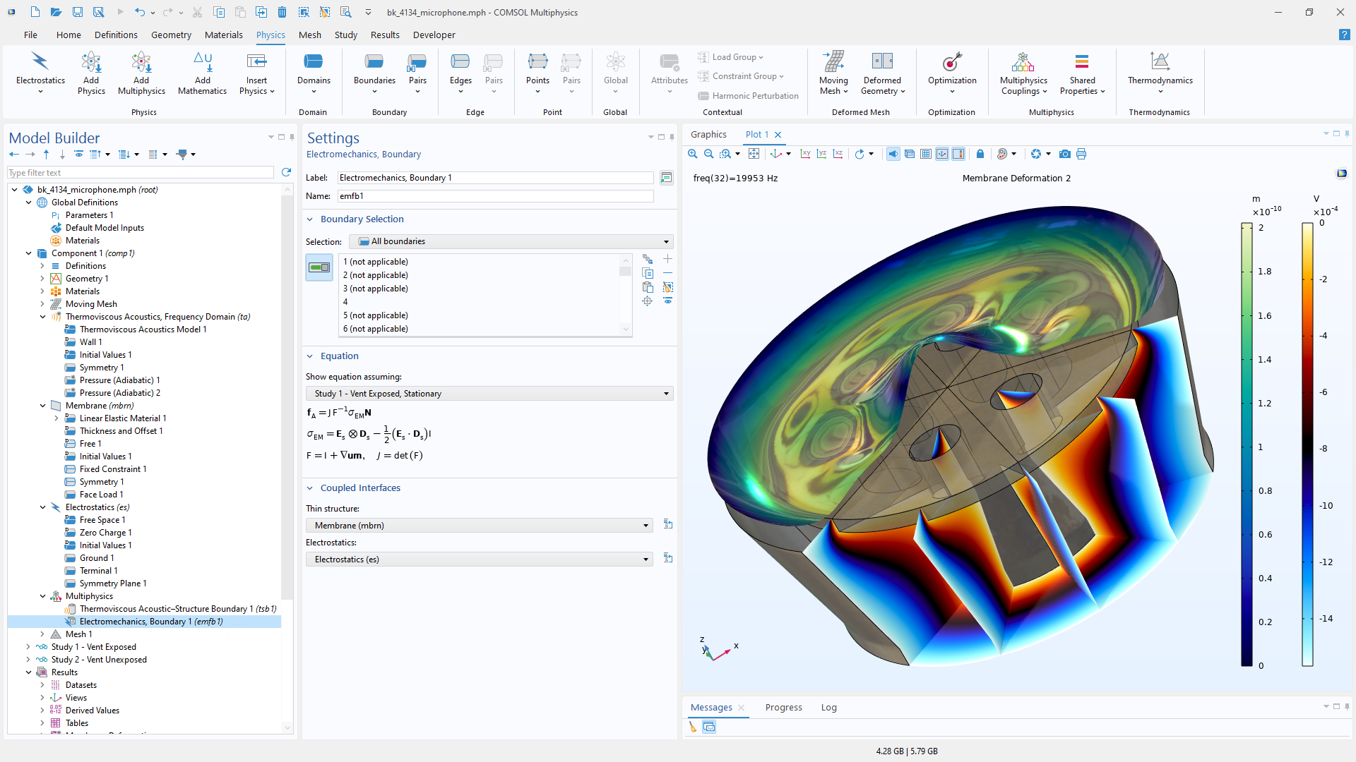
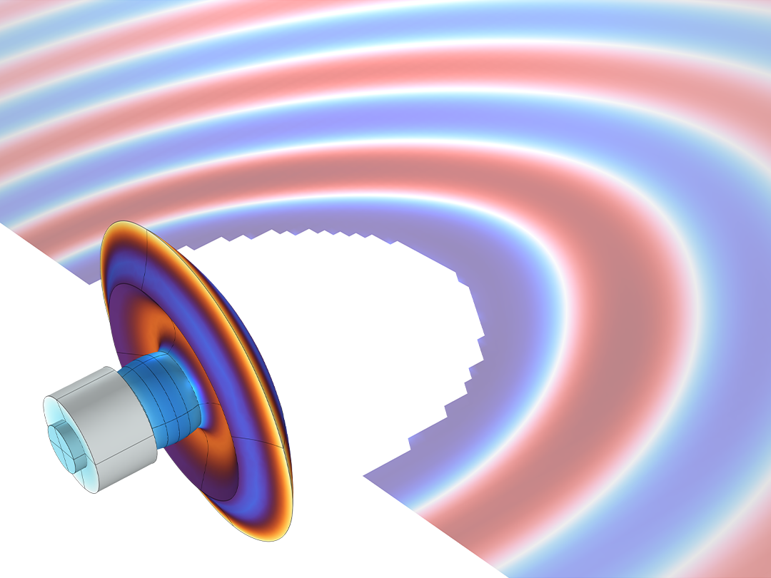
電気音響トランスデューサーなどなどのモデリングに, 体積構造荷重として使用される電流誘導ローレンツ力.
磁場にさらされたときの磁性材料の形状の変化で, ソナーやトランスフォーマーのノイズにとって重要.
金属および誘電体部品を含む圧電デバイスをモデル化.
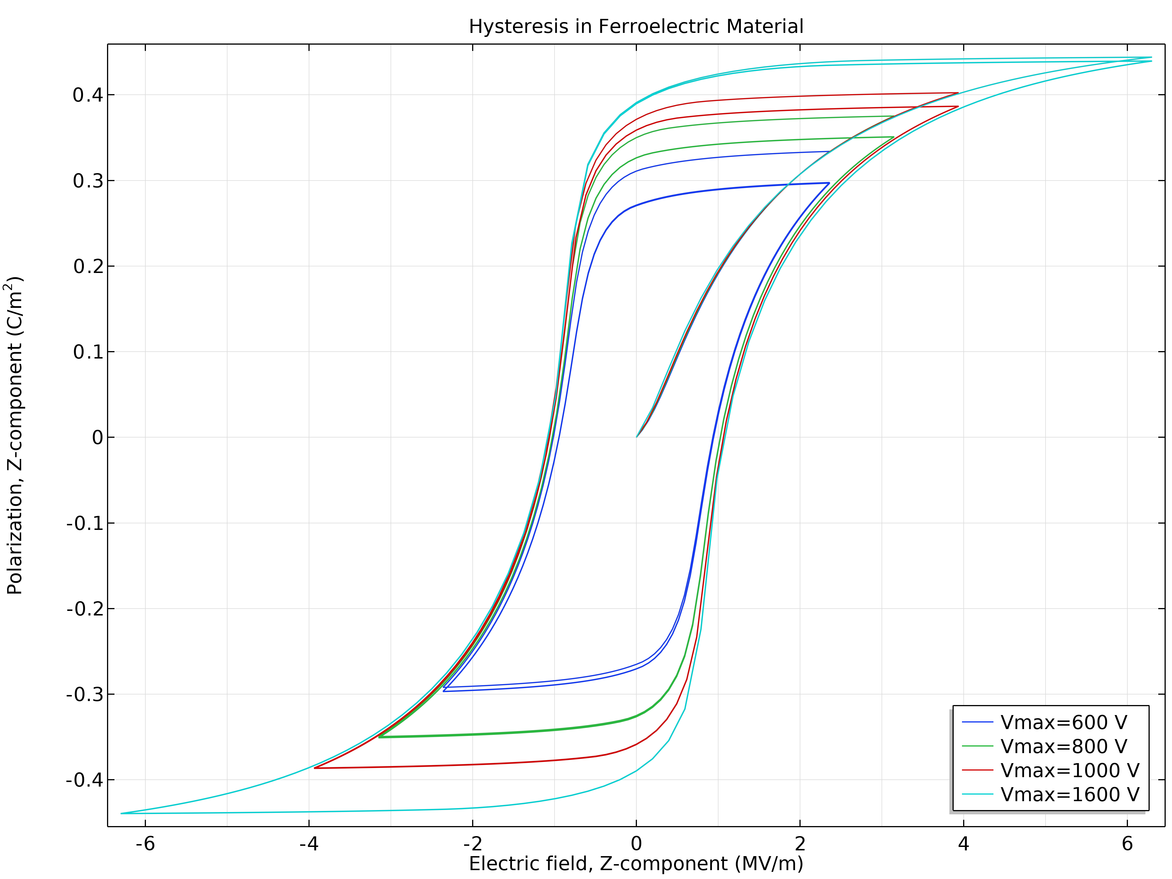
時間的に変化する分極をモデル化するために用いられる強誘電体の機能.
電磁場と導電性流体との相互作用をモデル化.
半導体のプロセスで使用される誘導結合プラズマ.
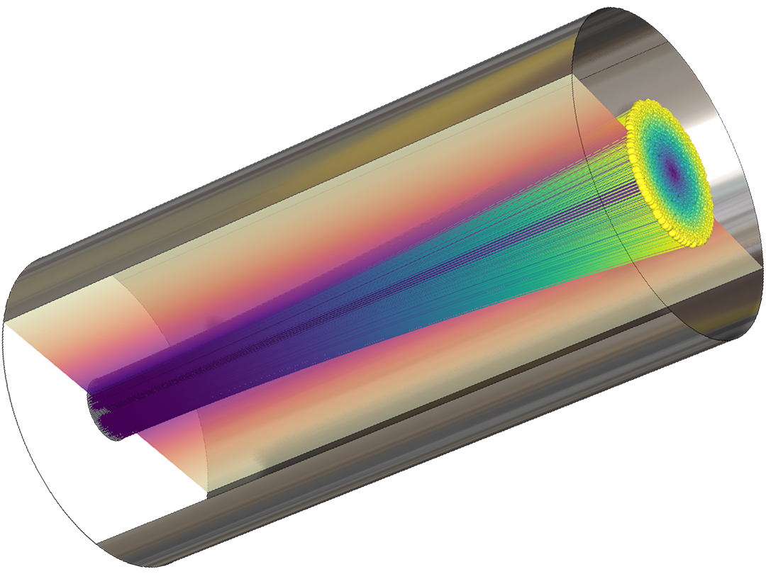
電磁力による荷電粒子または磁性粒子の運動.
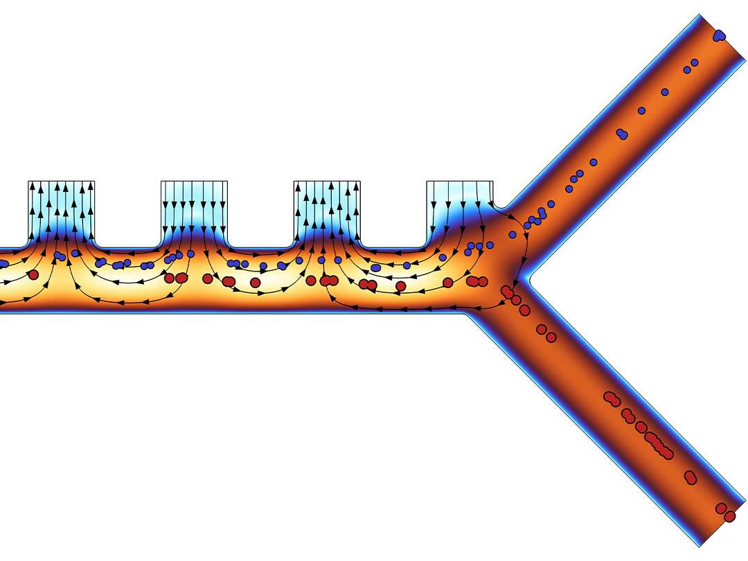
電界勾配による中性粒子の運動.

電磁解析をパラメーター最適化, 形状最適化, トポロジ最適化と組み合わせ可能.
MATLAB® ソフトウェアを使用すると, MATLAB® スクリプトと関数を使用して COMSOL Multiphysics® のシミュレーションを簡単に実行できます. LiveLink™ for MATLAB® インターフェース製品を使用すると, MATLAB® 環境内で COMSOL® の操作に直接アクセスし, 既存の MATLAB® コードと調和させることができます.
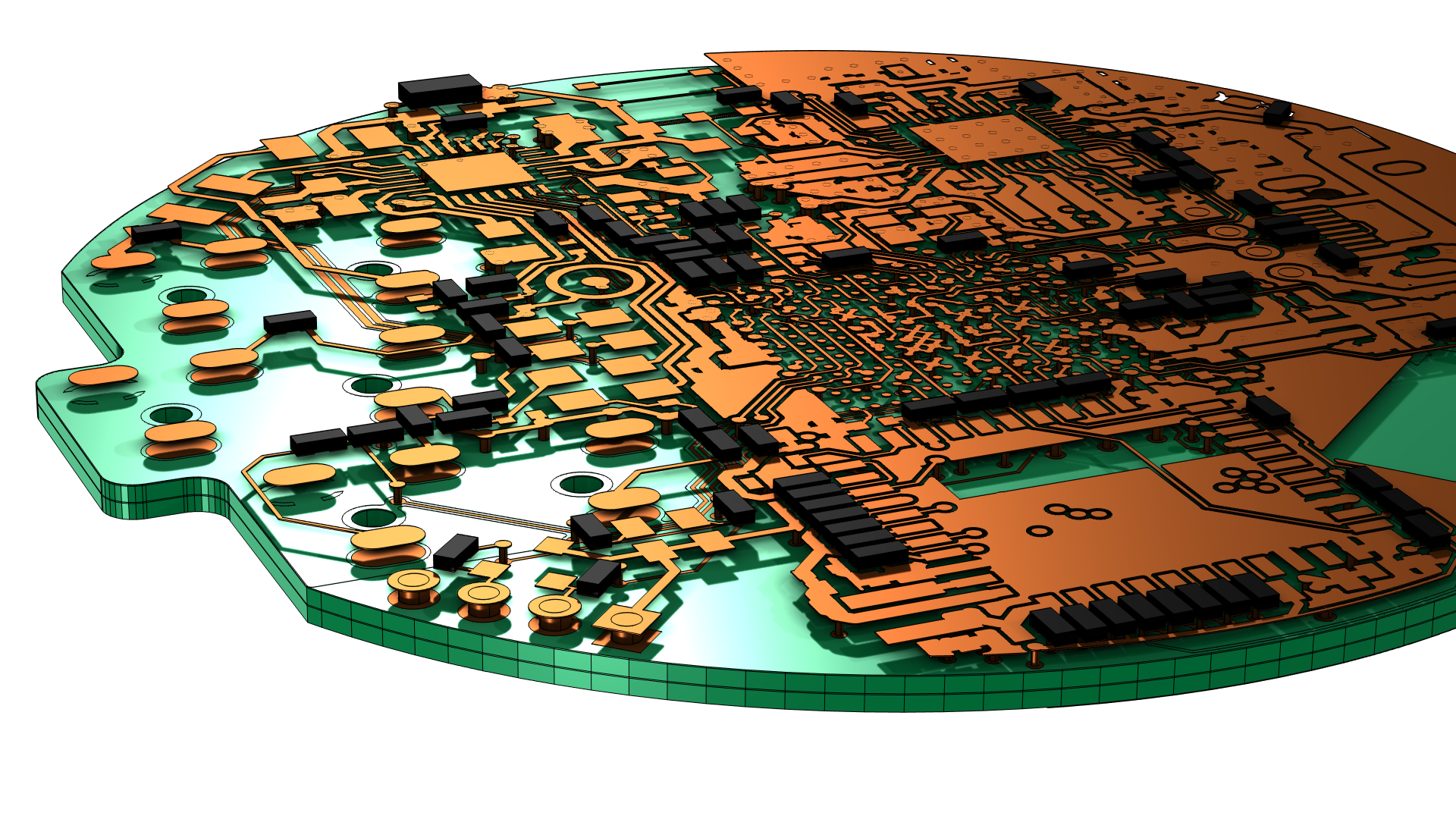
CAD モデルや電子回路のレイアウトの電磁気特性を簡単に解析できるように, COMSOL は主要な CAD システムのための ECAD インポートモジュール, CADインポートモジュール, デザインモジュール, LiveLink™ 製品を製品群の一部として提供しています.
また, LiveLink™ for Excel® により, Microsoft Excel® スプレッドシートのデータと COMSOL Multiphysics® 環境で定義したパラメーターを同期することができます.
シミュレーションのニーズはそれぞれ異なります.
ソフトウェアがお客様の要件を満たすかどうかを十分に評価するには, 当社までお問い合わせください. 営業担当者とご相談いただくことで, お客様の目的に合わせた推奨事項や, 評価を最大限に活用するための文書化されたモデル事例などをご提供します. お客様のニーズに最適なライセンスオプションの選択をサポートします.
"COMSOL へお問い合わせ" ボタンをクリックしてください. 連絡先情報, 具体的なご意見やご質問をご入力のうえ送信してください. 1営業日以内に営業担当者よりご連絡いたします.
ソフトウェアデモをリクエスト