RF Module Updates
For users of the RF Module, COMSOL Multiphysics® version 5.5 includes mixed-mode S-parameters, two new Port types, and a new specific absorption rate feature. Learn more about these features below.
Specific Absorption Rate
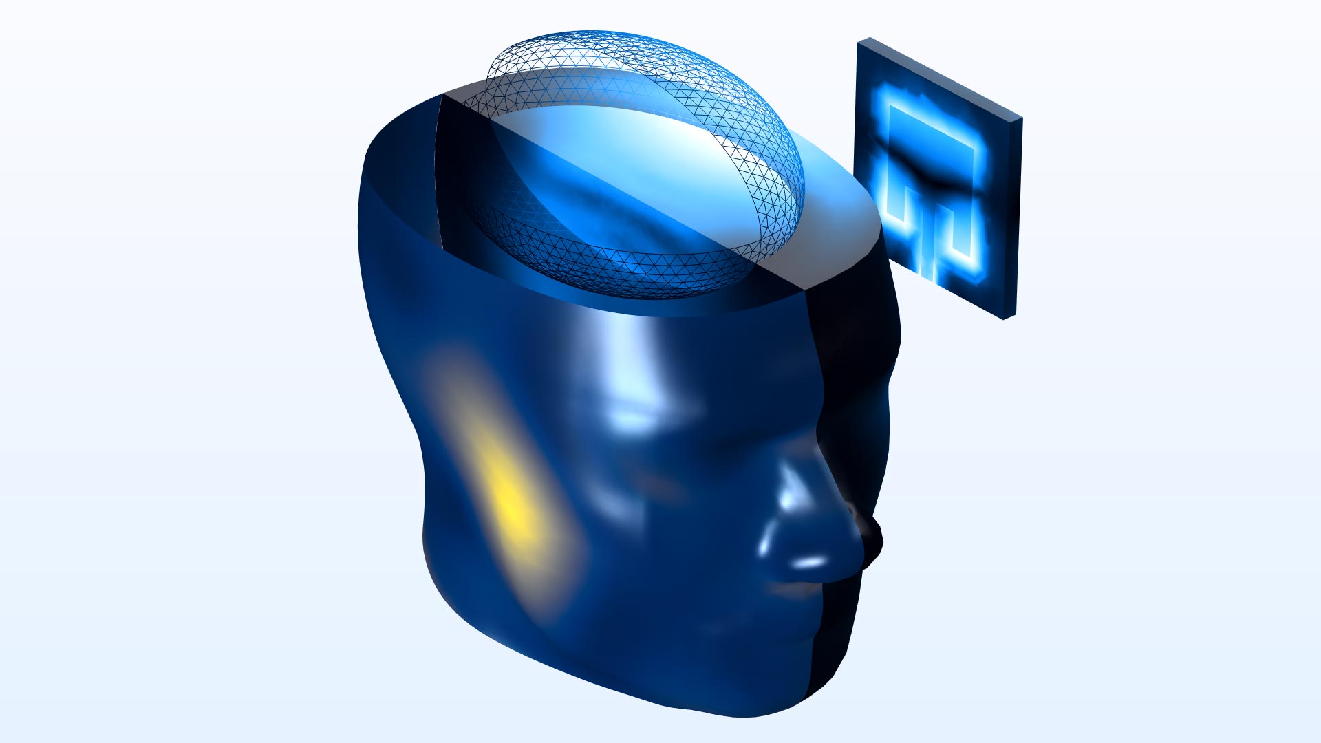
Users of consumer electronics with radiating devices are exposed to RF emission, and the amount of exposure is characterized by the specific absorption rate (SAR). The RF energy rate absorbed by tissue is represented by the SAR value and is now directly available as a predefined postprocessing variable. This new feature is demonstrated in the SAR of a Human Head Next to a Wi-Fi Antenna model.
Mixed-Mode S-Parameters
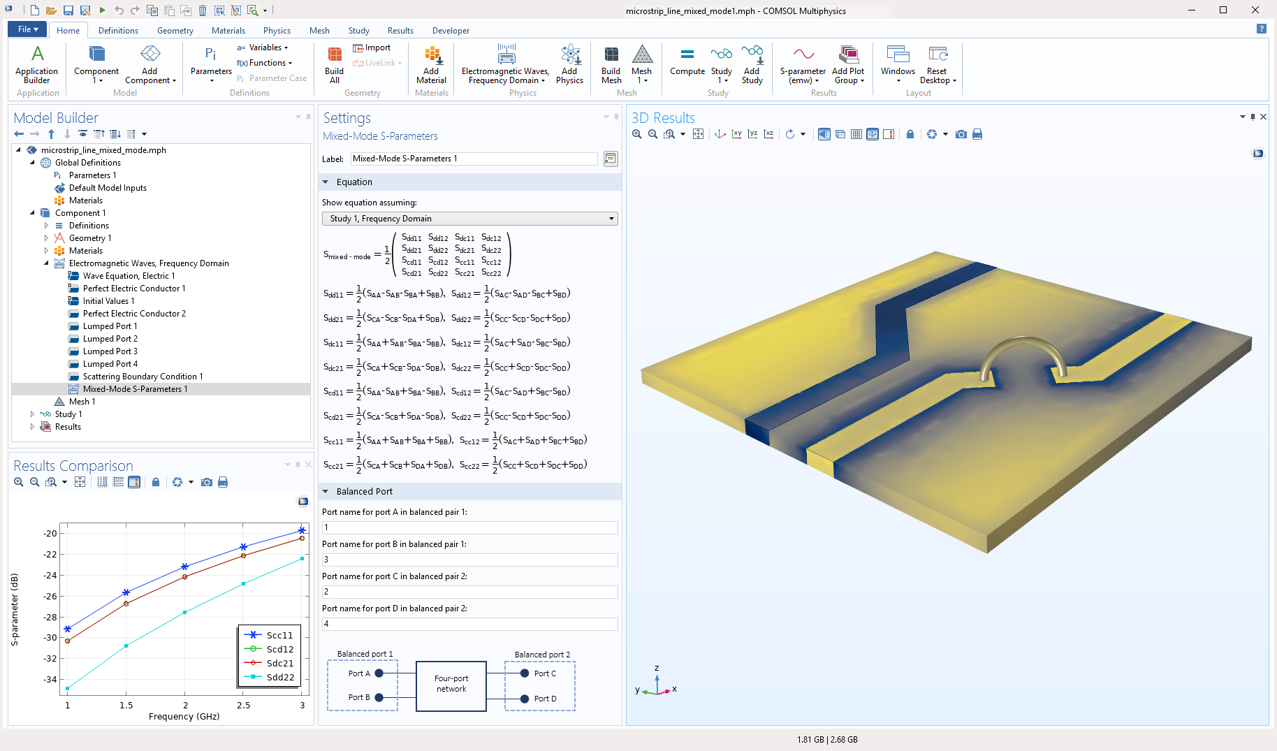
Mixed-mode S-parameters describe the response of a circuit with balanced ports excited and terminated by two mode types: common and differential modes. They are calculated using a full S-parameter matrix of a four-port network that is composed of four single-ended lines. You can see this new feature used in the Mixed-Mode S-Parameters Analysis model.
Full-Wave and Ray Optics Simulation Coupling
You can now run simultaneous full-wave and ray tracing simulations by combining the Ray Optics Module functionality with your RF Module simulations. This enables multiscale electromagnetic modeling, such as analyzing a waveguide beaming into a large room, where a full-wave simulation would be computationally prohibitive. To facilitate this coupling, two new features Release from Electric Field and Release from Far-Field Radiation Pattern have been added to the Geometrical Optics interface in the Ray Optics Module that release rays based on either a near or far field from a full-wave simulation. You can see these new features demonstrated in the Ray Optics with a Dipole Antenna Source (3D) and Ray Optics with a Dipole Antenna Source (2D Axisymmetric) models.
New Port Types
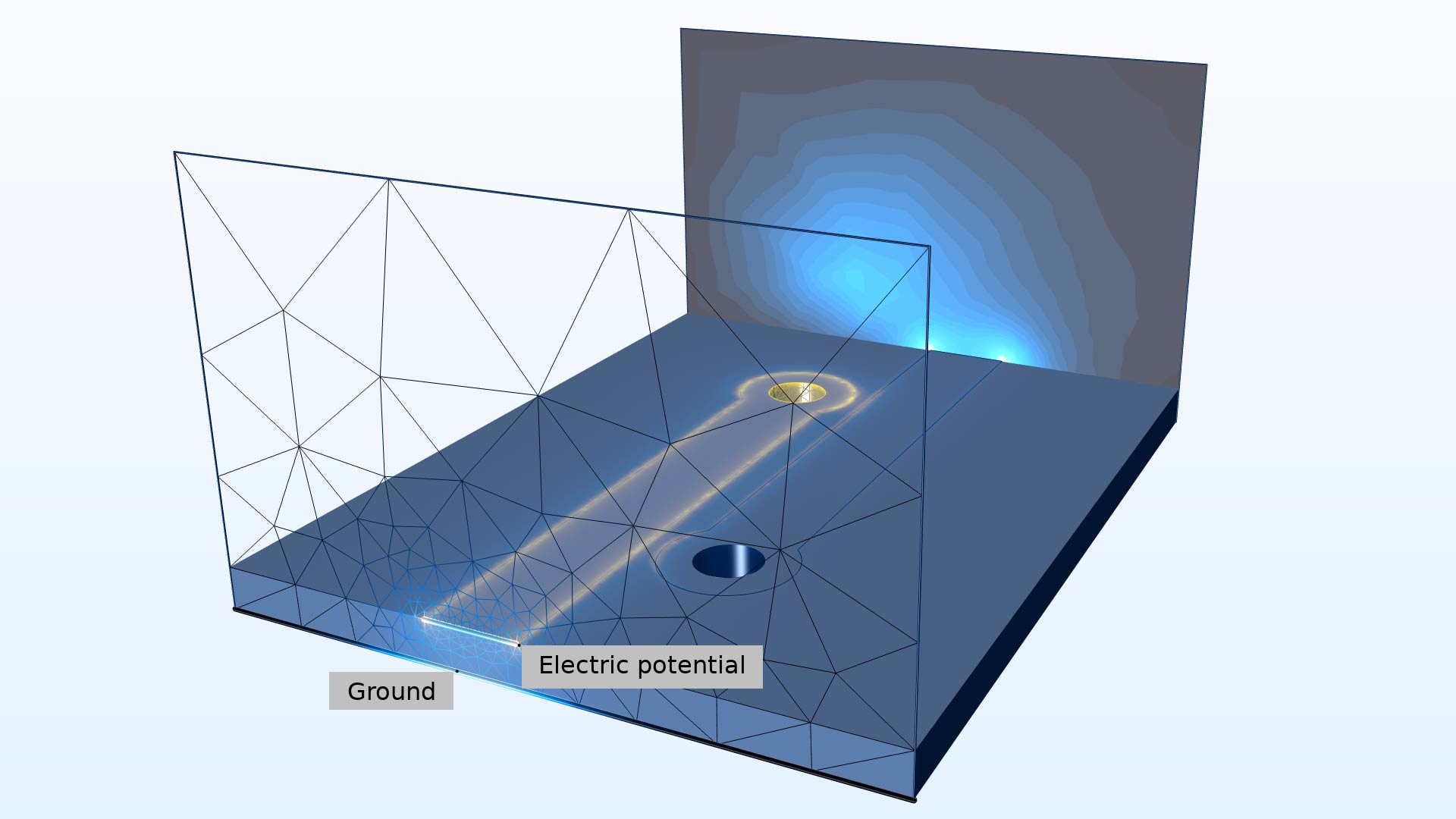
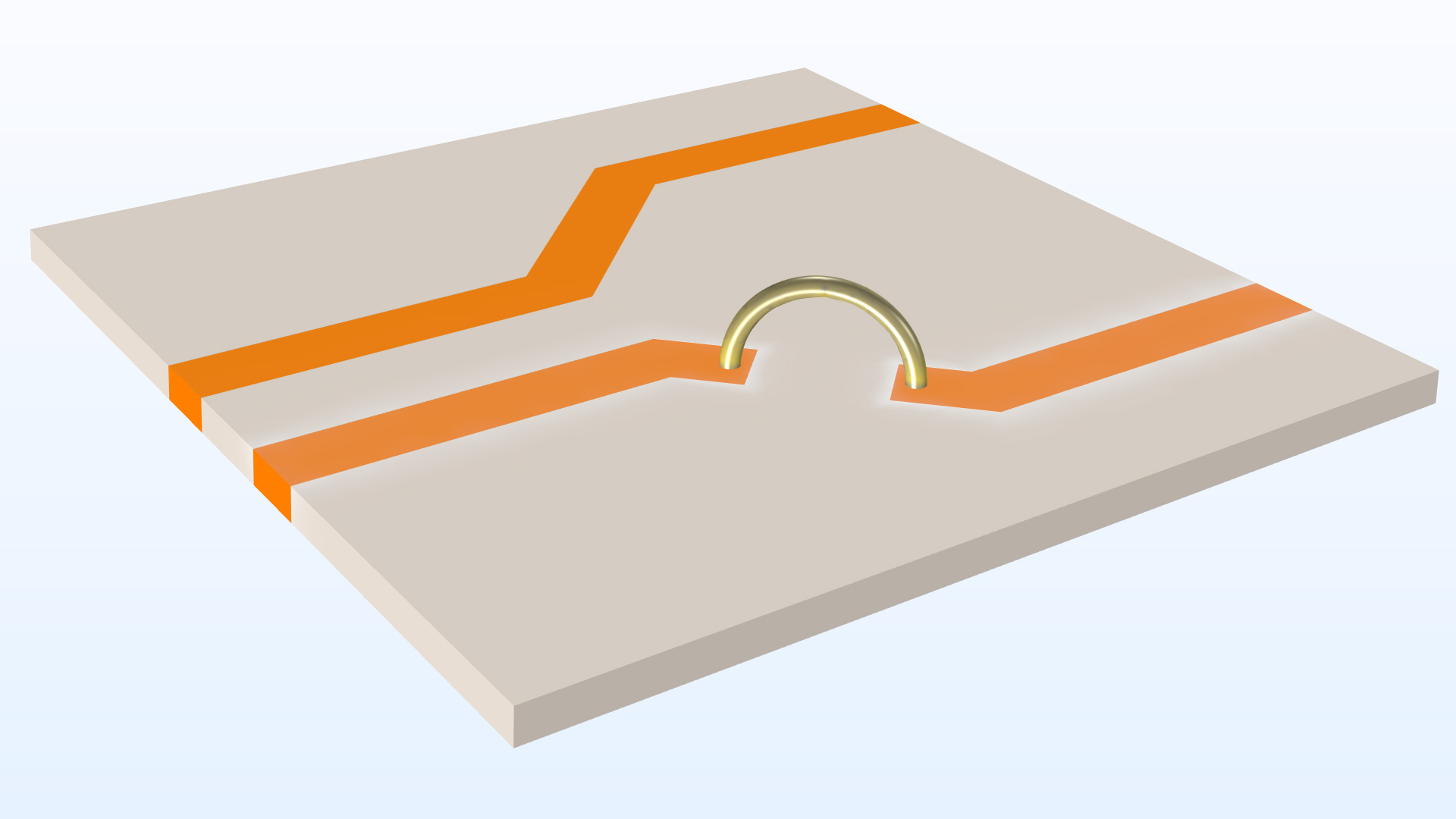
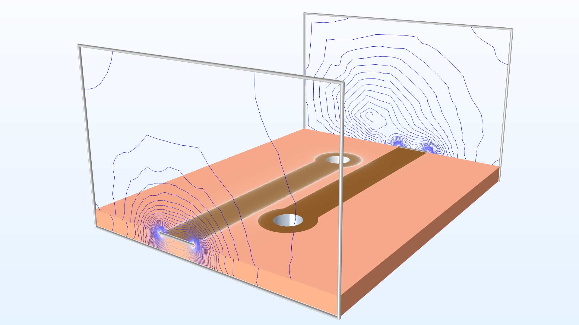
A Transverse electromagnetic (TEM) port boundary condition is typically used on each side of the modeling domain for a microstrip line and ground plane. The new TEM type of port is completed by adding electric potential and ground subfeatures. The edge of the microstrip line top trace on the TEM port boundary is set to electric potential, while the edge of the ground plane on the TEM port boundary is set to ground.
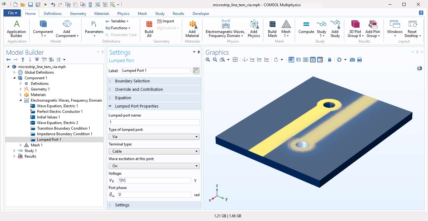
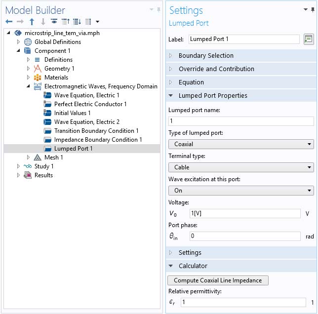
The new type of lumped port, Via, is useful for exciting or terminating the cylindrical shape formed by a via in a circuit board. A via is a metal conductor plated on the inside of a cylindrical hole that leads from one side of a circuit board to another. You can see these new features used in the Modeling of Microstrip Lines with Vias model.
Port Utility
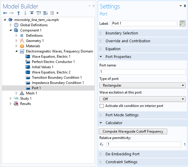
When designing a circuit with an arbitrarily sized feed structure, the cutoff frequency in a waveguide is often overlooked. As a result, the unwanted frequency may accidentally be part of the simulation resulting in unnecessarily long solution times. You can now calculate and remove those frequencies from the simulation. For the Lumped Port feature, you can compute the coaxial line impedance based on a user-defined relative permeability. For the Port feature, when using a rectangular or circular port, you can compute the waveguide cutoff frequency based on a user-defined relative permeability.
Additional Set of Material Properties
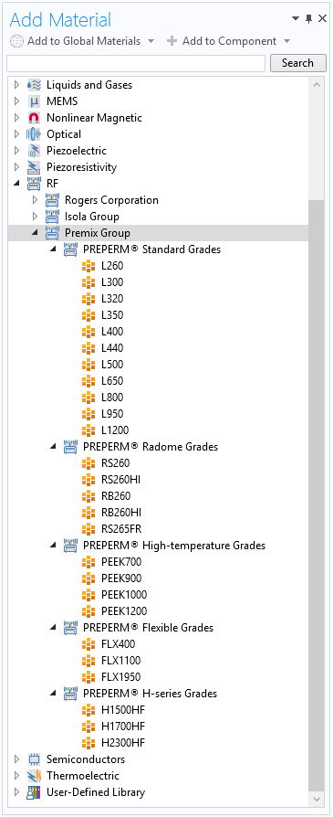
The material library within the RF Module has been extended with an additional 25 dielectric materials from the company Premix Group. The new materials can be used when modeling millimeter-wave devices for 5G, IoT, SatCom, automotive radar, and mmWave applications.
More Effective 3D Antenna Functions from 2D Axisymmetric Models
As an addition to the previously available far-field norm functions, a new set of 3D far-field gain and realized gain functions are available for 2D axisymmetric models. These new functions are useful for axisymmetric modeling of antennas with circular ports that have a positive azimuthal mode number. This new functionality makes 2D axisymmetric models more useful for the purpose of getting a quick estimate of the far-field response.
You can see this functionality demonstrated in the following models:
Plot S-Parameters While Solving
When you generate the default S-parameter results plot, the plot will now be updated as a frequency or a parametric sweep progresses in a way that is similar to that of a probe plot. This is useful for evaluating the intermediate performance of a large-sized model without running the simulation to its completion.
RF Module Add-Ins
As detailed on the Application Builder Release Highlights page, you can now build applications that perform specific tasks for general use and then load them into any MPH-file to which they are applicable. You can access two already built add-ins by going to the Developer tab and clicking the Add-in Libraries button.
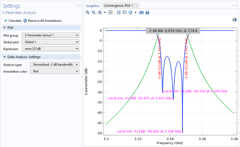
S-Parameter Analysis Add-In
This add-in helps you find the maxima, minima, and bandwidth, based on a dB-scaled S-parameter plot. You can use toolbar buttons in the Settings window to add annotations for calculated maxima, minima, and bandwidth, or to remove the annotations on the chosen 1D plot.
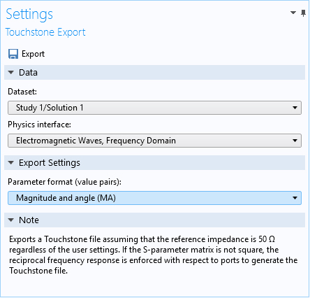
Touchstone Export Add-In
This add-in exports a Touchstone file using already available solutions. If the solution is not computed from a port sweep, the generated Touchstone file is based on reciprocal S-parameter responses. Use the toolbar button in the Settings window to export a Touchstone file, with a full S-parameter solution from a port sweep solution or reciprocal S-parameters for a single port excitation solution.
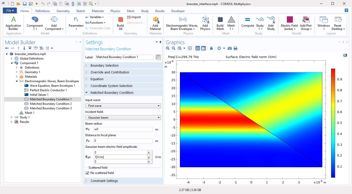
Gaussian Beam Input Option for Scattering and Matched Boundary Conditions
The Scattering and Matched boundary conditions have a new option for the Incident field combo box. Choosing the Gaussian beam option allows for propagation of a Gaussian beam in an arbitrary direction. The Gaussian beam is defined from the paraxial Gaussian beam formula. You can see this new functionality in the Gaussian Beam Incident at the Brewster Angle and Self-Focusing models.
Polarization Plots and Jones Vector Variables
Periodic ports now create a Polarization plot by default. The Polarization plot depicts the polarization state for the different diffraction orders and is based on new postprocessing variables for Jones vector elements. Also, the base vectors, used for defining the Jones vectors, are available for plotting and evaluation. You can see this new functionality in the Frequency-Selective Surface, Periodic Complementary Split Ring Resonator model.
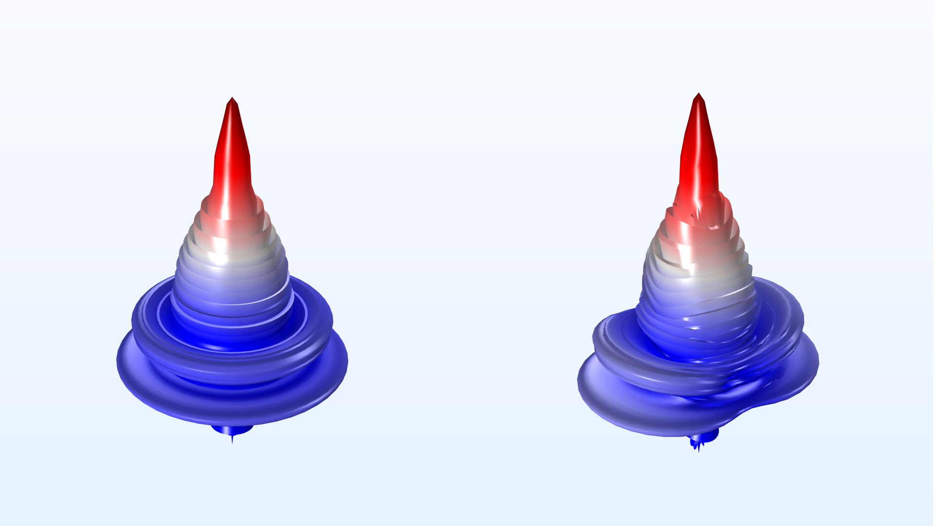
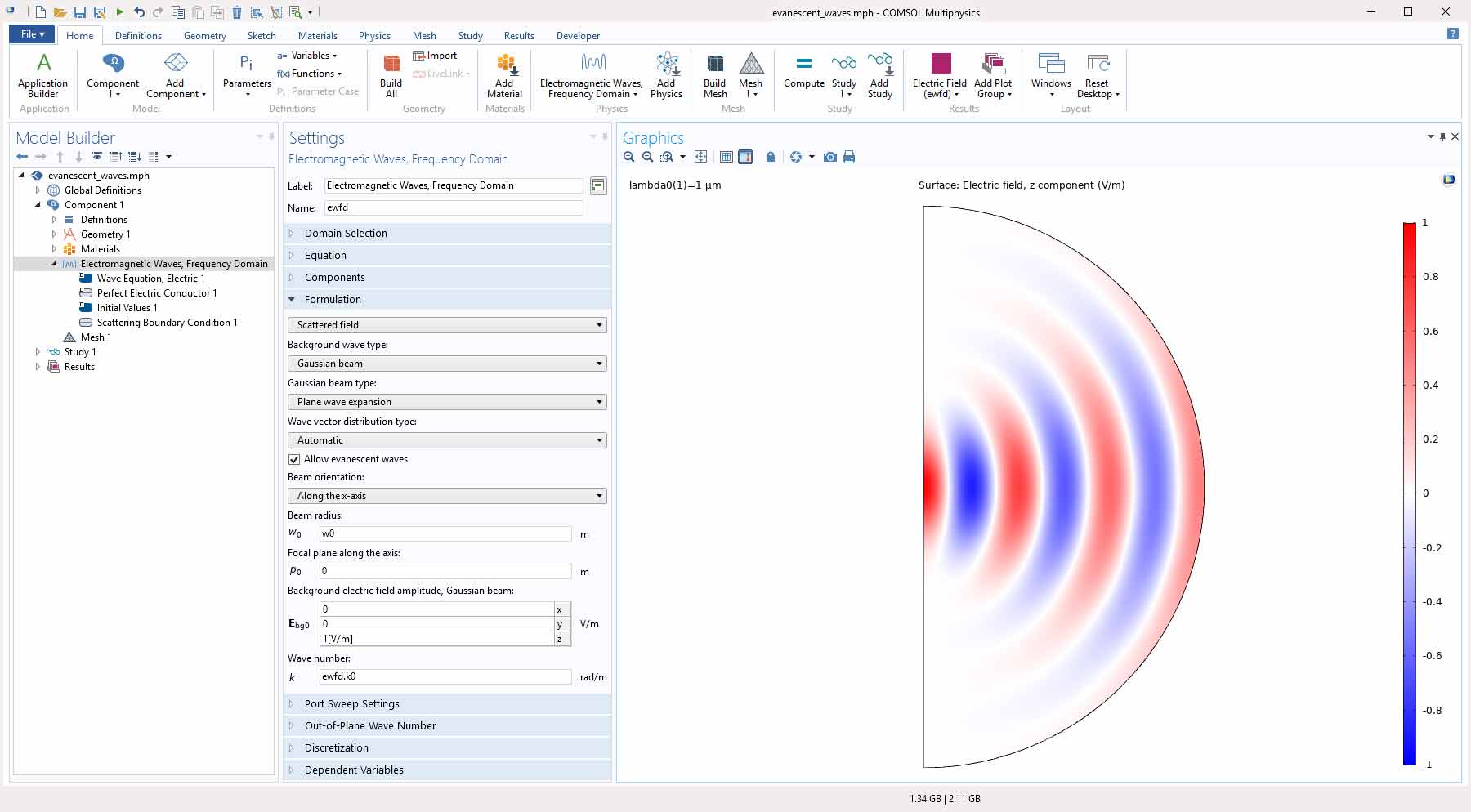
Evanescent Waves for Gaussian Beam Background Fields
When using the Plane wave expansion option for defining a Gaussian beam background field, evanescent waves can now be included in the expansion by checking an Allow evanescent waves box. This option can be useful when simulating a tightly focused Gaussian beam, where the spot radius is smaller than the wavelength, propagating away from the focus.
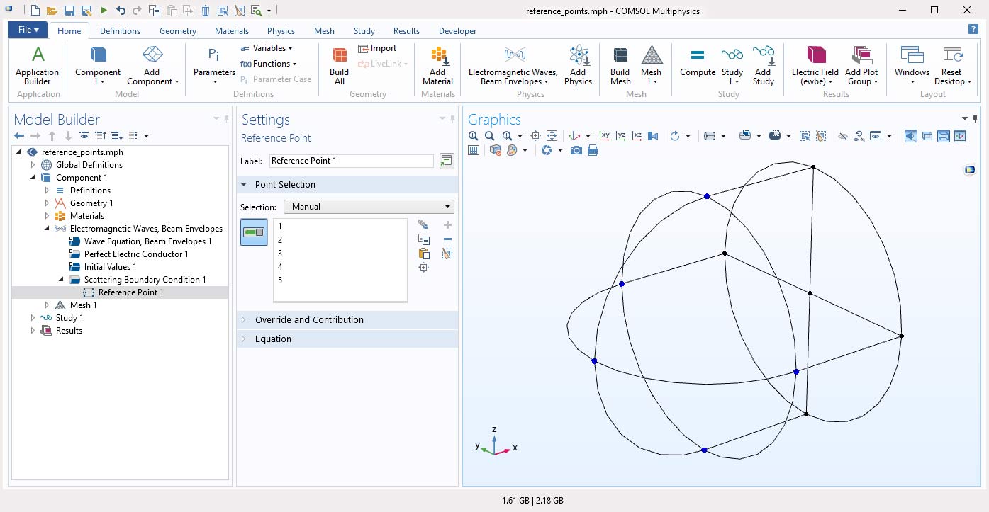
Reference Points for Scattering and Matched Boundary Conditions
The Reference Point attribute is now available for the Scattering Boundary Condition and Matched Boundary Condition for the Electromagnetic Waves, Frequency Domain and Electromagnetic Waves, Beam Envelopes interfaces, when an input field is active. The reference position is defined as the average position of the selected points. This feature is mainly useful when the domain material includes absorption or gain.
New Tutorial Models
Version 5.5 brings three new tutorial models.
SAR of a Human Head Next to a Wi-Fi Antenna

Application Library Title:
sar_wifi_antenna
Mixed-Mode S-Parameter Analysis
Application Library Title:
microstrip_line_mixed_mode
Modeling of Microstrip Lines with Vias
Application Library Title:
microstripline_tem_via
Download from the Application Gallery
PREPERM® is a registered trademark of Premix Oy.