Thermal-Stress Analysis of a Turbine Stator Blade
Application ID: 10476
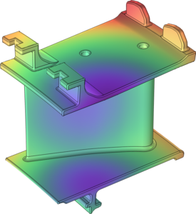
This example shows how to compute thermally induced stresses in a turbine stator blade using the Thermal Stress, Solid interface.
The conditions within gas turbines are extreme. The pressure can be as high as 40 bar, and the temperature more than 1000 K. Any new component must therefore be carefully designed to be able to withstand thermal stresses, vibrations and loads asserted by the fluid rushing through the turbine. If a component fails, the high rotational speeds can result in a complete rupture of the whole turbine. The most extreme conditions are found in the high pressure part downstream of the combustion chamber where hot combustion gases flows through a cascade of rotors and stators. To prevent the parts from melting, air is led from the compressor past the combustion chamber, and is used as a coolant. Directly behind the combustion chamber, both internal cooling and film cooling is applied. Further downstream, where the temperature is somewhat lower, it may suffice with internal cooling. Since the physics within a gas turbine is very complex, simplified approaches are often used at initial stages of the development of the new components. In this model, the thermal stresses in a stator blade with internal cooling are analyzed.
この model の例は, 通常次の製品を使用して構築されるこのタイプのアプリケーションを示しています.
ただし, これを完全に定義およびモデル化するには, 追加の製品が必要になる場合があります. さらに, この例は, 次の製品の組み合わせのコンポーネントを使用して定義およびモデル化することもできます.
- COMSOL Multiphysics® and
- either the CFD モジュール, or 伝熱モジュール and
- either the MEMS モジュール, or 構造力学モジュール
アプリケーションのモデリングに必要な COMSOL® 製品の組み合わせは, 境界条件, 材料特性, フィジックスインターフェース, パーツライブラリなど, いくつかの要因によって異なります. 特定の機能が複数の製品に共通している場合もあります. お客様のモデリングニーズに適した製品の組み合わせを決定するために, 製品仕様一覧 を確認し, 無償のトライアルライセンスをご利用ください. COMSOL セールスおよびサポートチームでは, この件に関するご質問にお答えしています.